GF1A TRANSFER / 4WD / AWD DYNAMIC TORQUE CONTROL 4WD/AWD SYSTEM C1337/91 Diameter of the Tire is not Uniform
DESCRIPTION
The 4WD ECU assembly outputs this DTC if a difference in tire size is detected.
| DTC No. | Detection Item | DTC Detection Condition | Trouble Area |
|---|---|---|---|
| C1337/91 | Diameter of the Tire is not Uniform | When the following continues for 36 seconds or more:
At a vehicle speed of 30 km/h (18.6 mph) or more, the average speed difference between the front wheel and rear wheel is 4% or more. |
·
Tire size or pressure (front and rear tires) ·
Speed sensor circuit ·
Front speed sensor ·
Rear speed sensor ·
Front speed sensor rotor (Front axle hub sub-assembly) ·
Rear speed sensor rotor (Rear axle hub and bearing assembly) ·
Harness and connector ·
Skid control ECU (Brake actuator assembly) ·
4WD ECU assembly |
WIRING DIAGRAM
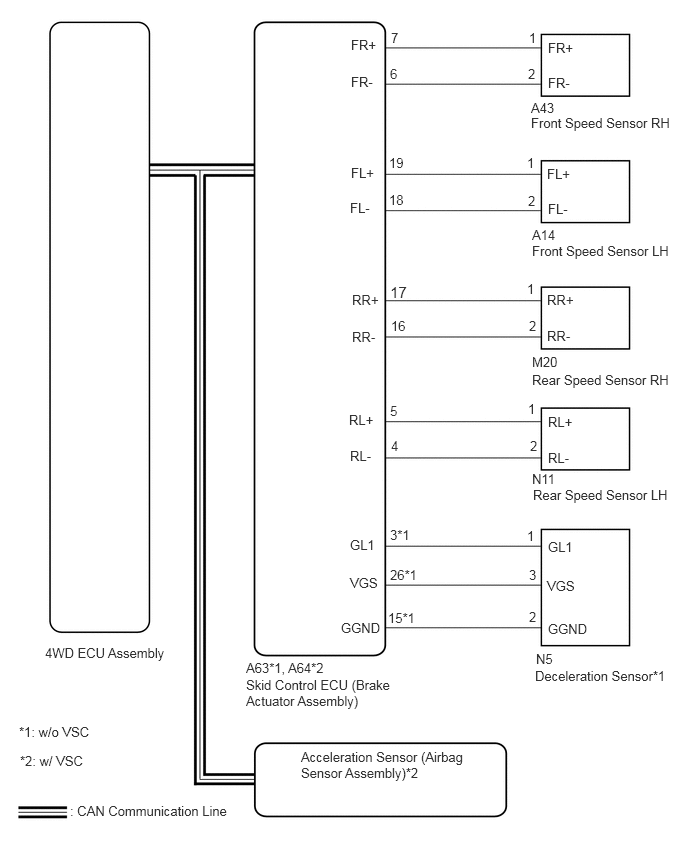
CAUTION / NOTICE / HINT
- HINT:
-
Check the condition of each related circuit connector before troubleshooting.
PROCEDURE
Check the size and condition of all 4 tires.
- HINT:
-
This DTC is output when tire deformation or a difference in tire size is detected.
- OK:
The diameter and air pressure of all 4 tires are the same.
- Result:
Proceed to OK NG
OK
NG
Clear the DTCs.
Click hereDrivetrain>GF1A TRANSFER / 4WD / AWD>DYNAMIC TORQUE CONTROL 4WD/AWD SYSTEM>DTC CHECK / CLEAR
- Chassis > Four Wheel Drive > Clear DTCs
- 50002 118
Start the engine.
Drive the vehicle at a speed of 20 km/h (12 mph) or more so that the same DTC is output.
Click hereDrivetrain>GF1A TRANSFER / 4WD / AWD>DYNAMIC TORQUE CONTROL 4WD/AWD SYSTEM>DTC CHECK / CLEAR
- Chassis > Four Wheel Drive > Trouble Codes
- 50001 118
Check if the speed sensor DTC (brake control system DTC) is output.
w/o VSC: Click hereBrake>BRAKE CONTROL / DYNAMIC CONTROL SYSTEMS>ANTI-LOCK BRAKE SYSTEM>DTC CHECK / CLEAR
w/ VSC: Click hereBrake>BRAKE CONTROL / DYNAMIC CONTROL SYSTEMS>VEHICLE STABILITY CONTROL SYSTEM>DTC CHECK / CLEAR
- Chassis > ABS/VSC/TRC > Trouble Codes
- 50001 105
Read the DTCs using the GTS.
- Result:
Result Proceed to Only "C1377/91" is output A DTC is not output B Speed sensor DTC (brake control system DTC) is output (w/o VSC) C Speed sensor DTC (brake control system DTC) is output (w/ VSC) D
A
B
Click hereGeneral>INTRODUCTION>HOW TO TROUBLESHOOT ECU CONTROLLED SYSTEMS>HOW TO PROCEED WITH TROUBLESHOOTING
C
Click hereBrake>BRAKE CONTROL / DYNAMIC CONTROL SYSTEMS>ANTI-LOCK BRAKE SYSTEM>DIAGNOSTIC TROUBLE CODE CHART
D
Make sure that there is no looseness at the locking part and the connecting part of the connectors.
Turn the power switch off.
w/o VSC:
Disconnect the A63 skid control ECU (brake actuator assembly) connector.
w/ VSC:
Disconnect the A64 skid control ECU (brake actuator assembly) connector.
Disconnect the A14, A43, M20 and/or N11 speed sensor connector(s).
Measure the resistance according to the value(s) in the table below.
- Standard Resistance (w/o VSC):
for Front RH: Tester Connection Condition Specified Condition A63-7 (FR+) - A43-1 (FR+) Always Below 1 Ω A63-7 (FR+) or A43-1 (FR+) - Body ground Always 10 kΩ or higher A63-6 (FR-) - A43-2 (FR-) Always Below 1 Ω A63-6 (FR-) or A43-2 (FR-) - Body ground Always 10 kΩ or higher
for Front LH: Tester Connection Condition Specified Condition A63-19 (FL+) - A14-1 (FL+) Always Below 1 Ω A63-19 (FL+) or A14-1 (FL+) - Body ground Always 10 kΩ or higher A63-18 (FL-) - A14-2 (FL-) Always Below 1 Ω A63-18 (FL-) or A14-2 (FL-) - Body ground Always 10 kΩ or higher
for Rear RH: Tester Connection Condition Specified Condition A63-17 (RR+) - M20-1 (RR+) Always Below 1 Ω A63-17 (RR+) or M20-1 (RR+) - Body ground Always 10 kΩ or higher A63-16 (RR-) - M20-2 (RR-) Always Below 1 Ω A63-16 (RR-) or M20-2 (RR-) - Body ground Always 10 kΩ or higher
for Rear LH: Tester Connection Condition Specified Condition A63-5 (RL+) - N11-1 (RL+) Always Below 1 Ω A63-5 (RL+) or N11-1 (RL+) - Body ground Always 10 kΩ or higher A63-4 (RL-) - N11-2 (RL-) Always Below 1 Ω A63-4 (RL-) or N11-2 (RL-) - Body ground Always 10 kΩ or higher
- Standard Resistance (w/ VSC):
for Front RH: Tester Connection Condition Specified Condition A64-7 (FR+) - A43-1 (FR+) Always Below 1 Ω A64-7 (FR+) or A43-1 (FR+) - Body ground Always 10 kΩ or higher A64-6 (FR-) - A43-2 (FR-) Always Below 1 Ω A64-6 (FR-) or A43-2 (FR-) - Body ground Always 10 kΩ or higher
for Front LH: Tester Connection Condition Specified Condition A64-19 (FL+) - A14-1 (FL+) Always Below 1 Ω A64-19 (FL+) or A14-1 (FL+) - Body ground Always 10 kΩ or higher A64-18 (FL-) - A14-2 (FL-) Always Below 1 Ω A64-18 (FL-) or A14-2 (FL-) - Body ground Always 10 kΩ or higher
for Rear RH: Tester Connection Condition Specified Condition A64-17 (RR+) - M20-1 (RR+) Always Below 1 Ω A64-17 (RR+) or M20-1 (RR+) - Body ground Always 10 kΩ or higher A64-16 (RR-) - M20-2 (RR-) Always Below 1 Ω A64-16 (RR-) or M20-2 (RR-) - Body ground Always 10 kΩ or higher
for Rear LH: Tester Connection Condition Specified Condition A64-5 (RL+) - N11-1 (RL+) Always Below 1 Ω A64-5 (RL+) or N11-1 (RL+) - Body ground Always 10 kΩ or higher A64-4 (RL-) - N11-2 (RL-) Always Below 1 Ω A64-4 (RL-) or N11-2 (RL-) - Body ground Always 10 kΩ or higher
- Result:
Proceed to OK NG
OK
NG
Turn the ignition switch off.
Perform the sensor check in the Test Mode procedure.
w/o VSC: Click hereBrake>BRAKE CONTROL / DYNAMIC CONTROL SYSTEMS>ANTI-LOCK BRAKE SYSTEM>TEST MODE PROCEDURE
w/ VSC: Click hereBrake>BRAKE CONTROL / DYNAMIC CONTROL SYSTEMS>VEHICLE STABILITY CONTROL SYSTEM>TEST MODE PROCEDURE
- Chassis > ABS/VSC/TRC > Utility
-
Tester Display Signal Check - 50005 105 3
- OK:
All Test Mode DTCs are cleared.
- Result:
Proceed to OK NG
OK
NG
Clear the DTCs.
Click hereDrivetrain>GF1A TRANSFER / 4WD / AWD>DYNAMIC TORQUE CONTROL 4WD/AWD SYSTEM>DTC CHECK / CLEAR
- Chassis > Four Wheel Drive > Clear DTCs
- 50002 118
Start the engine.
Drive the vehicle at a speed of 20 km/h (12 mph) or more and check that the same DTC is output.
Click hereDrivetrain>GF1A TRANSFER / 4WD / AWD>DYNAMIC TORQUE CONTROL 4WD/AWD SYSTEM>DTC CHECK / CLEAR
- Chassis > Four Wheel Drive > Trouble Codes
- 50001 118
- Result:
Proceed to DTC is output (w/o VSC) DTC is output (w/ VSC) DTC is not output
DTC is output (w/o VSC)
DTC is output (w/ VSC)
DTC is not output
Click hereGeneral>INTRODUCTION>HOW TO TROUBLESHOOT ECU CONTROLLED SYSTEMS>HOW TO PROCEED WITH TROUBLESHOOTING
Turn the ignition switch off.
Remove the front speed sensor rotor (front axle hub sub-assembly) or rear speed sensor rotor (rear axle hub and bearing assembly).
For front: Click hereDrivetrain>AXLE AND DIFFERENTIAL>FRONT AXLE HUB>REMOVAL
For rear: Click hereDrivetrain>AXLE AND DIFFERENTIAL>REAR AXLE HUB>REMOVAL
Check the speed sensor rotor.
- OK:
No scratches, oil, or foreign matter on the rotors.
- NOTICE:
-
Check the speed sensor signal after cleaning or replacement.
-
w/o VSC: Click hereBrake>BRAKE CONTROL / DYNAMIC CONTROL SYSTEMS>ANTI-LOCK BRAKE SYSTEM>TEST MODE PROCEDURE
-
w/ VSC: Click hereBrake>BRAKE CONTROL / DYNAMIC CONTROL SYSTEMS>VEHICLE STABILITY CONTROL SYSTEM>TEST MODE PROCEDURE
- HINT:
- ·
If the front speed sensor rotor needs to be replaced, replace it together with the front axle hub sub-assembly.
·If the rear speed sensor rotor needs to be replaced, replace it together with the rear axle hub and bearing assembly.
- Result:
Proceed to OK NG
OK
NG
Turn the ignition switch off.
Replace the front speed sensor or the rear speed sensor.
For front: Click hereBrake>BRAKE CONTROL / DYNAMIC CONTROL SYSTEMS>FRONT SPEED SENSOR>REMOVAL
For rear: Click hereBrake>BRAKE CONTROL / DYNAMIC CONTROL SYSTEMS>REAR SPEED SENSOR(for 4WD/AWD)>REMOVAL
- NOTICE:
-
Check the speed sensor signal after replacement.
-
w/o VSC: Click hereBrake>BRAKE CONTROL / DYNAMIC CONTROL SYSTEMS>ANTI-LOCK BRAKE SYSTEM>TEST MODE PROCEDURE
-
w/ VSC: Click hereBrake>BRAKE CONTROL / DYNAMIC CONTROL SYSTEMS>VEHICLE STABILITY CONTROL SYSTEM>TEST MODE PROCEDURE
- Result:
Proceed to NEXT
NEXT
Clear the DTC.
Click hereDrivetrain>GF1A TRANSFER / 4WD / AWD>DYNAMIC TORQUE CONTROL 4WD/AWD SYSTEM>DTC CHECK / CLEAR
- Chassis > Four Wheel Drive > Clear DTCs
- 50002 118
Start the engine.
Drive the vehicle at a speed of 20 km/h (12 mph) or more and check that the same DTC is output.
Click hereDrivetrain>GF1A TRANSFER / 4WD / AWD>DYNAMIC TORQUE CONTROL 4WD/AWD SYSTEM>DTC CHECK / CLEAR
- Chassis > Four Wheel Drive > Trouble Codes
- 50001 118
- Result:
Proceed to DTC is output DTC is not output
- HINT:
-
Reinstall the sensor, connectors, etc. and restore the vehicle to its prior condition before rechecking DTCs.
DTC is output
DTC is not output
Replace the brake actuator assembly.
w/o VSC: Click hereBrake>BRAKE CONTROL / DYNAMIC CONTROL SYSTEMS>BRAKE ACTUATOR(w/o VSC)>REMOVAL
w/ VSC: Click hereBrake>BRAKE CONTROL / DYNAMIC CONTROL SYSTEMS>BRAKE ACTUATOR(w/ VSC)>REMOVAL
- Result:
Proceed to NEXT
NEXT
Clear the DTC.
Click hereDrivetrain>GF1A TRANSFER / 4WD / AWD>DYNAMIC TORQUE CONTROL 4WD/AWD SYSTEM>DTC CHECK / CLEAR
- Chassis > Four Wheel Drive > Clear DTCs
- 50002 118
Start the engine.
Drive the vehicle at a speed of 20 km/h (12 mph) or more and check that the same DTC is output.
Click hereDrivetrain>GF1A TRANSFER / 4WD / AWD>DYNAMIC TORQUE CONTROL 4WD/AWD SYSTEM>DTC CHECK / CLEAR
- Chassis > Four Wheel Drive > Trouble Codes
- 50001 118
- Result:
Proceed to DTC is output DTC is not output
DTC is output
DTC is not output