DOOR LOCK FRONT DOOR LOCK INSTALLATION
CAUTION / NOTICE / HINT
- HINT:
- ·
Use the same procedure for the RH and LH sides.
·The procedure listed below is for the LH side.
·A bolt without a torque specification is shown in the standard bolt chart.
Click hereGeneral>SPECIFICATIONS>STANDARD BOLT>SPECIFIED TORQUE FOR STANDARD BOLTS
PROCEDURE

 69720B
1.INSTALL FRONT DOOR LOCK REMOTE CONTROL CABLE ASSEMBLY LH
69760C
2.INSTALL FRONT DOOR INSIDE LOCKING CABLE ASSEMBLY LH
69040A
3.INSTALL FRONT DOOR WITH MOTOR LOCK ASSEMBLY LH
- NOTICE:
- ·
When reusing the removed front door lock assembly, replace the door lock wiring harness seal on the connector with a new one.
·Do not allow grease or dust to adhere to the door lock wiring harness seal surface of the connector.
·Reusing the door lock wiring harness seal or using a damaged door lock wiring harness seal may cause water intrusion. This may result in a malfunction of the front door lock assembly.
Apply MP grease to the sliding parts of the front door with motor lock assembly LH.
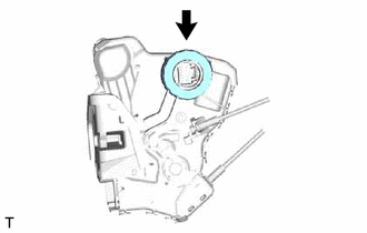
Install a new door lock wiring harness seal to the front door with motor lock assembly LH.
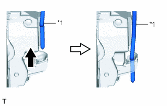
| *1 | Front Door Lock Open Rod LH |

|
Upward |
Insert the front door lock open rod LH into the front door with motor lock assembly LH.
Make sure that the front door lock open rod is securely connected to the front door with motor lock assembly LH.
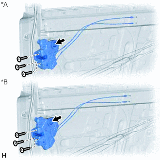
| *A | w/o Double Locking System |
| *B | w/ Double Locking System |
Using a T30 "TORX" socket wrench, install the front door with motor lock assembly LH with the 3 screws.
- Torque:
- 5.0 N*m (51 kgf*cm, 44 in.*lbf)
Connect the connector.
69217F
4.INSTALL FRONT DOOR OUTSIDE HANDLE COVER LH (for Driver Side)
67404F
5.INSTALL FRONT DOOR REAR LOWER FRAME SUB-ASSEMBLY LH
68151D
6.INSTALL FRONT DOOR GLASS RUN LH
68102
7.INSTALL FRONT DOOR GLASS SUB-ASSEMBLY LH
67832
8.INSTALL FRONT DOOR SERVICE HOLE COVER LH
67602
9.INSTALL FRONT DOOR TRIM BOARD SUB-ASSEMBLY LH
69284C
10.INSTALL FRONT DOOR INSIDE HANDLE BEZEL PLUG LH
74646A
11.INSTALL DOOR ASSIST GRIP COVER LH
12.INSTALL POWER WINDOW REGULATOR SWITCH ASSEMBLY WITH FRONT DOOR ARMREST BASE PANEL (for Front Passenger Side)
13.INSTALL POWER WINDOW REGULATOR MASTER SWITCH ASSEMBLY WITH FRONT DOOR ARMREST BASE PANEL (for Driver Side)
67492A
14.INSTALL FRONT DOOR LOWER FRAME BRACKET GARNISH LH
15.CONNECT CABLE TO NEGATIVE BATTERY TERMINAL
- NOTICE:
-
When disconnecting the cable, some systems need to be initialized after the cable is reconnected.
-
Click hereGeneral>INTRODUCTION>REPAIR INSTRUCTION>INITIALIZATION
16.CHECK SRS WARNING LIGHT (w/ Side Airbag)
17.INITIALIZE POWER WINDOW CONTROL SYSTEM (w/ Jam Protection Function)
18.CHECK POWER WINDOW CONTROL SYSTEM
19.CHECK POWER DOOR LOCK CONTROL SYSTEM