METER / GAUGE / DISPLAY METER / GAUGE SYSTEM Speedometer Malfunction
DESCRIPTION
The combination meter assembly receives vehicle speed signals from the brake actuator assembly (skid control ECU) via the CAN communication line. The wheel speed sensors output voltages that vary according to the vehicle speed. The brake actuator assembly (skid control ECU) supplies power to the wheel speed sensors. The brake actuator assembly (skid control ECU) calculates the vehicle speed based on the pulses of the voltage.
WIRING DIAGRAM
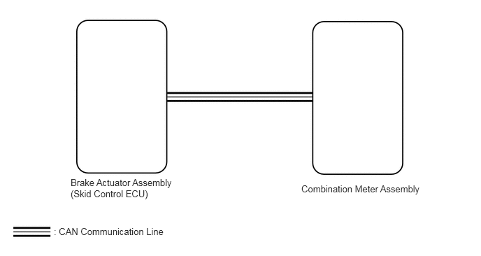
CAUTION / NOTICE / HINT
- NOTICE:
- ·
If the vehicle speed is outside the allowable range when tested, perform the on-vehicle inspection (See page Vehicle Interior>METER / GAUGE / DISPLAY>METER / GAUGE SYSTEM>OPERATION CHECK).
·When replacing the combination meter assembly, make sure to replace it with a new one.
- HINT:
-
Before starting the following inspection, check the tire size and tire air pressure.
PROCEDURE
Check if a CAN communication system DTC is output.
for LHD: Click herePower Source / Network>NETWORKING>CAN COMMUNICATION SYSTEM(for LHD)>DIAGNOSIS SYSTEM
for RHD: Click herePower Source / Network>NETWORKING>CAN COMMUNICATION SYSTEM(for RHD)>DIAGNOSIS SYSTEM
- Result:
Proceed to CAN communication system DTC is not output CAN communication system DTC is output (for LHD) CAN communication system DTC is output (for RHD)
CAN communication system DTC is not output
CAN communication system DTC is output (for LHD)
CAN communication system DTC is output (for RHD)
*1: w/o VSC
*2: w/ VSC
Check if an anti-lock brake system*1 or vehicle stability control system*2 DTC is output.
Anti-lock brake system: Click hereBrake>BRAKE CONTROL / DYNAMIC CONTROL SYSTEMS>ANTI-LOCK BRAKE SYSTEM>DTC CHECK / CLEAR
Vehicle stability control system: Click hereBrake>BRAKE CONTROL / DYNAMIC CONTROL SYSTEMS>VEHICLE STABILITY CONTROL SYSTEM>DTC CHECK / CLEAR
- Chassis > ABS/VSC/TRC > Trouble Codes
- 50001 105
- Result:
Proceed to DTC is not output Anti-lock brake system DTC is output (w/o VSC) Vehicle stability control system DTC is output (w/ VSC)
DTC is not output
Anti-lock brake system DTC is output (w/o VSC)
Vehicle stability control system DTC is output (w/ VSC)
Using the GTS, perform the Active Test.
Click hereVehicle Interior>METER / GAUGE / DISPLAY>METER / GAUGE SYSTEM>DATA LIST / ACTIVE TEST
- Body Electrical > Combination Meter > Active Test
-
Tester Display Measurement Item Control Range Diagnostic Note Speed Meter Operation Speedometer OFF, 0, 40, 80, 120, 160 or 200 (km/h or mph) Acceptable range (km/h or mph): [Control range → Speedometer display]
for km/h·40 → 41.7 to 46.2
·80 → 83.4 to 88.4
·120 → 125.1 to 130.6
·160 → 166.2 to 173.2
·200 → 207.7 to 215.7
for mph·40 → 40 to 43.5
·80 → 80 to 84.5
·120 → 100 to 125.5
- Body Electrical > Combination Meter > Active Test
-
Tester Display Speed Meter Operation - 50004 122 1
- OK:
Speedometer indication is normal.
- Result:
Proceed to OK NG
OK
NG
Using the GTS, read the Data List.
Click hereVehicle Interior>METER / GAUGE / DISPLAY>METER / GAUGE SYSTEM>DATA LIST / ACTIVE TEST
- Body Electrical > Combination Meter > Data List
-
Tester Display Measurement Item Range Normal Condition Diagnostic Note Vehicle Speed Meter Vehicle speed Min.: 0 mph (0 km/h), Max.: 255 km/h (158 mph) Almost same as actual vehicle speed measured using a speedometer tester -
- Chassis > ABS/VSC/TRC > Data List
-
Tester Display Measurement Item Range Normal Condition Diagnostic Note Vehicle Speed Vehicle speed Min.: 0 mph (0 km/h), Max.: 326 km/h (202 mph) Almost same as actual vehicle speed measured using a speedometer tester -
- Body Electrical > Combination Meter > Data List
-
Tester Display Vehicle Speed Meter - 50003 122 8
- Chassis > ABS/VSC/TRC > Data List
-
Tester Display Vehicle Speed - 50003 105 42
- HINT:
- ·
When the Data List values of the ECUs match, an internal malfunction of the combination meter assembly is suspected.
·When the Data List values of the ECUs do not match, a signal output error of the brake actuator assembly (skid control ECU) or an internal malfunction of the combination meter assembly is suspected.
- Result:
Proceed to The Data List values of the ECUs match The Data List values of the ECUs do not match
The Data List values of the ECUs match
The Data List values of the ECUs do not match
Replace the combination meter assembly with a new or normally functioning one.
Click hereVehicle Interior>METER / GAUGE / DISPLAY>COMBINATION METER>REMOVAL
Check that the operation of the speedometer returns to nomal.
- OK:
The operation of the speedometer returns to normal.
- Result:
Proceed to OK NG (w/o VSC) NG (w/ VSC)
OK
NG (w/o VSC)
NG (w/ VSC)