CLUTCH CLUTCH MASTER CYLINDER(for LHD) INSTALLATION
PROCEDURE

 31453
1.INSTALL CLUTCH MASTER CYLINDER PUSH ROD CLEVIS
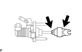
Install the lock nut to the clutch master cylinder assembly.
Install the clutch master cylinder push rod clevis to the clutch master cylinder assembly.
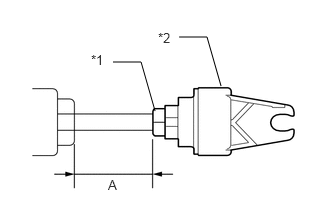
| *1 | Lock Nut |
| *2 | Clutch Master Cylinder Push Rod Clevis |
Tighten the lock nut and check that dimension A is the same as the dimension A that has been measured.
- Torque:
- 12 N*m (122 kgf*cm, 9 ft.*lbf)
- NOTICE:
-
When tightening the lock nut, be sure to hold the clevis in place by its square portion.
31459
2.INSTALL CLUTCH MASTER CYLINDER BRACKET
Install the clutch master cylinder bracket to the clutch master cylinder assembly.
31410
3.INSTALL CLUTCH MASTER CYLINDER ASSEMBLY
Install the clutch master cylinder assembly with the 2 nuts.
- Torque:
- 13 N*m (133 kgf*cm, 10 ft.*lbf)
31453A
4.CONNECT CLUTCH MASTER CYLINDER PUSH ROD CLEVIS WITH HOLE PIN
31481
5.CONNECT CLUTCH MASTER CYLINDER TO FLEXIBLE HOSE TUBE
Using a union nut wrench, connect the clutch master cylinder to flexible hose tube.
- Torque:
- 15 N*m (153 kgf*cm, 11 ft.*lbf)
- NOTICE:
-
Use the formula to calculate special torque values for situations where a union nut wrench is combined with a torque wrench (See page General>INTRODUCTION>REPAIR INSTRUCTION>PRECAUTION).
31434
6.CONNECT CLUTCH RESERVOIR TUBE
Connect the clutch reservoir tube to the clutch master cylinder assembly, and slide the clamp to secure it.
- NOTICE:
- ·
Connect the clutch reservoir tube so that it will not be twisted.
·Face the yellow mark upward.
73900
7.INSTALL LOWER NO. 1 INSTALL INSTRUMENT PANEL AIRBAG ASSEMBLY (w/ Driver Side Knee Airbag)
55432B
8.INSTALL LOWER INSTRUMENT PANEL FINISH PANEL (w/o Driver Side Knee Airbag)
55606
9.INSTALL NO. 1 INSTRUMENT PANEL UNDER COVER SUB-ASSEMBLY (w/o Driver Side Knee Airbag)
55736D
10.INSTALL COWL BODY MOUNTING REINFORCEMENT LH
Install the cowl body mounting reinforcement LH with the 2 nuts.
- Torque:
- 50 N*m (510 kgf*cm, 37 ft.*lbf)
55701J
11.INSTALL OUTER COWL TOP PANEL SUB-ASSEMBLY
85110
12.INSTALL WINDSHIELD WIPER MOTOR ASSEMBLY
89871A
13.INSTALL INJECTOR DRIVER
14.INSPECT SRS WARNING LIGHT
15.BLEED CLUTCH PIPE LINE
for 1AD-FTV:
Click hereDrivetrain>CLUTCH>CLUTCH SYSTEM(for 1AD-FTV)>BLEEDING
for 2AD-FTV:
Click hereDrivetrain>CLUTCH>CLUTCH SYSTEM(for 2AD-FTV)>BLEEDING
for 2AR-FE:
Click hereDrivetrain>CLUTCH>CLUTCH SYSTEM(for 2AR-FE)>BLEEDING
for 3ZR-FE:
Click hereDrivetrain>CLUTCH>CLUTCH SYSTEM(for 3ZR-FE)>BLEEDING
for 3ZR-FAE:
Click hereDrivetrain>CLUTCH>CLUTCH SYSTEM(for 3ZR-FAE)>BLEEDING
47287
16.CHECK BRAKE FLUID
Click hereBrake>BRAKE SYSTEM (OTHER)>BRAKE FLUID>BLEEDING
- HINT:
- ·
Check for leakage in the brake system.
·Check for leakage in the clutch system.
47287
17.CHECK FLUID LEVEL IN RESERVOIR
31301
18.INSPECT AND ADJUST CLUTCH PEDAL SUB-ASSEMBLY