AUDIO / VIDEO RADIO ANTENNA CORD(for Roof Side) INSTALLATION
PROCEDURE

 86101D
1.INSTALL NO. 3 ANTENNA CORD SUB-ASSEMBLY
Attach the 3 clamps to install the No. 3 antenna cord sub-assembly.
Install the bolt.
- Torque:
- 4.5 N*m (46 kgf*cm, 40 in.*lbf)
Connect each connector.
86101J
2.INSTALL NO. 2 ANTENNA CORD SUB-ASSEMBLY
Apply new double-sided tape as shown in the illustration.
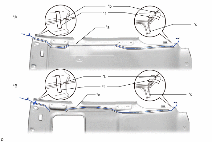
| *A | w/o Sliding Roof | *B | w/ Sliding Roof |
| *1 | One-sided Tape | - | - |
| *a | Double-sided Tape Application Marking | *b | Positioning Tape |
| *c | Surplus Cord Area | - | - |
Align the positioning tape for the front side of the antenna cord with the edge of the double-sided tape application marking and attach it as shown in the illustration.
Align the positioning tape for the rear side of the antenna cord with the edge of the double-sided tape application marking and attach it as shown in the illustration.
- HINT:
-
Place any extra antenna cord length in the surplus cord area shown in the illustration.
Secure both ends of the antenna cord using one-sided tape as shown in the illustration.
63310
3.INSTALL ROOF HEADLINING ASSEMBLY
4.CONNECT CABLE TO NEGATIVE BATTERY TERMINAL
- NOTICE:
-
When disconnecting the cable, some systems need to be initialized after the cable is reconnected.
-
Click hereGeneral>INTRODUCTION>REPAIR INSTRUCTION>INITIALIZATION
5.CHECK SRS WARNING LIGHT