INTERIOR PANELS / TRIM ROOF HEADLINING INSTALLATION
CAUTION / NOTICE / HINT
- HINT:
- ·
Use the same procedure for RHD and LHD vehicles.
·The procedure listed below is for LHD vehicles.
·A bolt without a torque specification is shown in the standard bolt chart.
Click hereGeneral>SPECIFICATIONS>STANDARD BOLT>SPECIFIED TORQUE FOR STANDARD BOLTS
PROCEDURE

 66425B
1.INSTALL REAR NO. 2 SIDE RAIL SPACER LH (w/o Curtain Shield Airbag)
Attach the 3 clips to install the rear No. 2 side rail spacer LH.
66415B
2.INSTALL REAR NO. 2 SIDE RAIL SPACER RH (w/o Curtain Shield Airbag)
- HINT:
-
Use the same procedure described for the LH side.
66425B
3.INSTALL REAR NO. 2 SIDE RAIL SPACER LH (w/ Curtain Shield Airbag)
Attach the 2 clips to install the rear No. 2 side rail spacer LH.
Attach the wire harness clamp.
Connect the rear part of the curtain shield airbag assembly LH with a new clip.
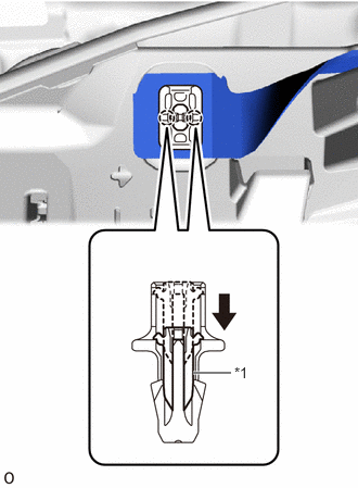
| *1 | Pin |
Push in the pin to lock the clip.
Check that the curtain shield airbag assembly LH is not twisted.
66415B
4.INSTALL REAR NO. 2 SIDE RAIL SPACER RH (w/ Curtain Shield Airbag)
- HINT:
-
Use the same procedure described for the LH side.
66424
5.INSTALL REAR SIDE RAIL SPACER LH (w/o Curtain Shield Airbag)
Attach the 4 clips to install the rear side rail spacer LH.
66414A
6.INSTALL REAR SIDE RAIL SPACER RH (w/o Curtain Shield Airbag)
- HINT:
-
Use the same procedure described for the LH side.
66424
7.INSTALL REAR SIDE RAIL SPACER LH (w/ Curtain Shield Airbag)
Attach the clip to install the rear side rail spacer LH.
Install the bolt.
Install the curtain shield airbag assembly LH.
Click hereVehicle Interior>SUPPLEMENTAL RESTRAINT SYSTEMS>CURTAIN SHIELD AIRBAG ASSEMBLY>INSTALLATION
66414A
8.INSTALL REAR SIDE RAIL SPACER RH (w/ Curtain Shield Airbag)
- HINT:
-
Use the same procedure described for the LH side.
66423A
9.INSTALL FRONT SIDE RAIL SPACER LH (w/o Curtain Shield Airbag)
Attach the 4 clips to install the front side rail spacer LH.
66413C
10.INSTALL FRONT SIDE RAIL SPACER RH (w/o Curtain Shield Airbag)
- HINT:
-
Use the same procedure described for the LH side.
63310
11.INSTALL ROOF HEADLINING ASSEMBLY
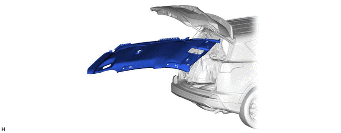
w/o Sliding Roof:
Place the roof headlining assembly into the vehicle as shown in the illustration.
- NOTICE:
-
Be careful not to damage the roof headlining assembly when placing it.
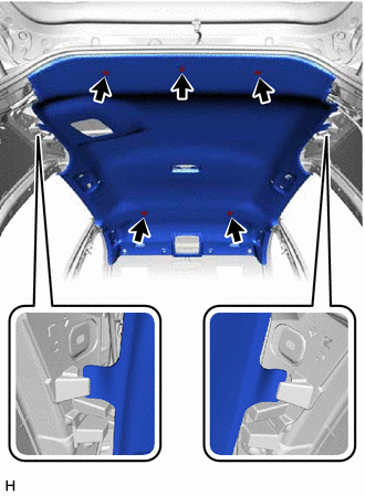
Install the roof headlining assembly with the 5 clips.
w/ Sliding Roof:
Place the roof headlining assembly into the vehicle as shown in the illustration.
- NOTICE:
-
Be careful not to damage the roof headlining assembly when placing it.
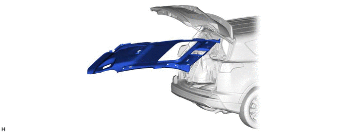
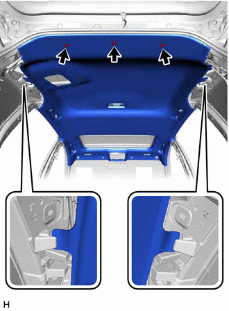
Install the roof headlining assembly with the 3 clips.
Attach the 3 wire harness clamps and connect the 2 connectors to the front pillar LH.
Attach the 4 wire harness clamps to the front pillar RH.
Connect the connector to the rear pillar RH.
w/ Sliding Roof:
Connect the connector.
w/ EC Mirror:
Connect the connector.
w/ Rain Sensor, w/o Pre-crash Safety System:
Connect the connector.
w/ Rain Sensor, w/ Pre-crash Safety System:
Connect the connector.
w/ Pre-crash Safety System:
Connect the connectors.
63318C
12.INSTALL SUN ROOF OPENING TRIM MOULDING (w/ Sliding Roof)
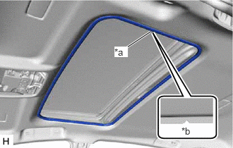
| *a | Sun Roof Opening Trim Moulding Paint Mark |
| *b | Cutout of the Roof Headlining Assembly |
Install the sun roof opening trim moulding as shown in the illustration.
87834
13.INSTALL INNER REAR VIEW MIRROR STAY HOLDER COVER (w/ EC Mirror)
89943
14.INSTALL RAIN SENSOR COVER (w/ Rain Sensor)
86466D
15.INSTALL NO. 1 FORWARD RECOGNITION COVER (w/ Pre-crash Safety System)
86466E
16.INSTALL NO. 2 FORWARD RECOGNITION COVER (w/ Pre-crash Safety System)
81240
17.INSTALL NO. 1 ROOM LIGHT ASSEMBLY
74610A
18.INSTALL ASSIST GRIP SUB-ASSEMBLY
- HINT:
-
Use the same procedure for all assist grip assemblies.
Install the 2 clips and 2 assist grip covers to the assist grip.
Attach the 2 clips to install the assist grip assembly.
81260A
19.INSTALL MAP LIGHT ASSEMBLY
74348
20.INSTALL VISOR HOLDER
- HINT:
-
Use the same procedure for both visor holders.
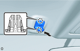
Attach the 2 claws.
Push in the visor holder to install it.
74320
21.INSTALL VISOR ASSEMBLY LH
Install the visor assembly LH with the 2 screws.
74310
22.INSTALL VISOR ASSEMBLY RH
- HINT:
-
Use the same procedure described for the LH side.
23.INSTALL UPPER INSTRUMENT PANEL
62212
24.INSTALL FRONT PILLAR GARNISH LH (w/o Curtain Shield Airbag)
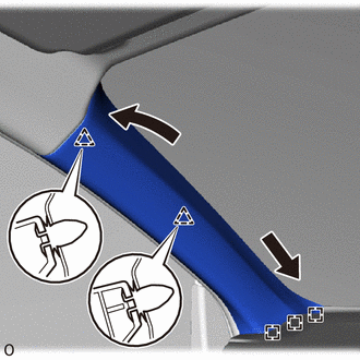
Attach the 3 guides.
Attach the upper part of the front pillar garnish assembly LH and the 2 clips to install the front pillar garnish LH.
62211
25.INSTALL FRONT PILLAR GARNISH RH (w/o Curtain Shield Airbag)
- HINT:
-
Use the same procedure described for the LH side.
62212
26.INSTALL FRONT PILLAR GARNISH LH (w/ Curtain Shield Airbag)
Install the front pillar garnish clips to the front pillar garnish LH.
- HINT:
-
Install the front pillar garnish clips so that it faces as shown in the illustration.
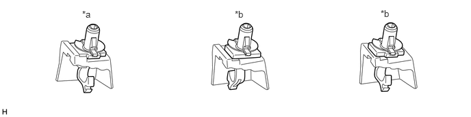
| *a | CORRECT | *b | INCORRECT |
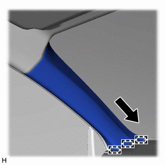
Attach the 3 guides.
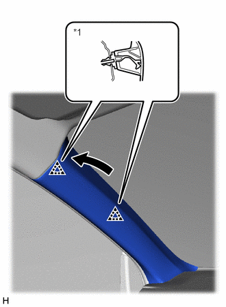
| *1 | Front Pillar Garnish Clip |
Attach the 2 front pillar garnish clips to install the front pillar garnish LH.
- HINT:
-
Make sure that the curtain shield airbag assembly LH is not pinched.
62211
27.INSTALL FRONT PILLAR GARNISH RH (w/ Curtain Shield Airbag)
- HINT:
-
Use the same procedure described for the LH side.
62412
28.INSTALL CENTER PILLAR GARNISH LH
Pass the front seat outer belt floor anchor through the hole of the center pillar garnish LH.
Attach the clip to install the center pillar garnish LH.
Install the 2 clips.
62411
29.INSTALL CENTER PILLAR GARNISH RH
- HINT:
-
Use the same procedure described for the LH side.
62414A
30.INSTALL LOWER CENTER PILLAR GARNISH LH
Attach the 2 claws and 2 clips to install the lower center pillar garnish LH.
Connect the front seat outer belt floor anchor with the bolt.
- Torque:
- 42 N*m (428 kgf*cm, 31 ft.*lbf)
73233
31.INSTALL OUTER LAP BELT ANCHOR COVER
62413A
32.INSTALL LOWER CENTER PILLAR GARNISH RH
- HINT:
-
Use the same procedure described for the LH side.
73135A
33.INSTALL SHOULDER BELT ANCHOR COVER RH
62480A
34.INSTALL INNER ROOF SIDE GARNISH ASSEMBLY LH
Attach the 8 clips to install the inner roof side garnish assembly LH.
Connect the rear seat outer belt shoulder anchor with the bolt.
- Torque:
- 42 N*m (428 kgf*cm, 31 ft.*lbf)
62470A
35.INSTALL INNER ROOF SIDE GARNISH ASSEMBLY RH
- HINT:
-
Use the same procedure described for the LH side.
73178A
36.INSTALL SEAT BELT ANCHOR COVER CAP
64740E
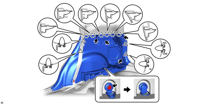
37.INSTALL DECK TRIM SIDE PANEL ASSEMBLY LH
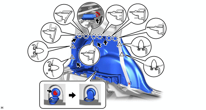
Connect the connector.
Attach the 4 clips and 6 claws to install the deck trim side panel assembly LH.
Install the luggage hold belt striker assembly with the bolt.
Install the tether anchor set bracket with the bolt.
Close the tether anchor set bracket cover.
Install the 2 bolts and screw.
64730J
38.INSTALL DECK TRIM SIDE PANEL ASSEMBLY RH
Attach the 4 clips and 6 claws to install the deck trim side panel assembly RH.
Install the luggage hold belt striker assembly with the bolt.
Install the tether anchor set bracket with the bolt.
Close the tether anchor set bracket cover.
Install the 2 bolts and screw.
64718A
39.INSTALL DECK TRIM SERVICE HOLE COVER
- HINT:
-
Use the same procedure for both deck trim service hole covers.
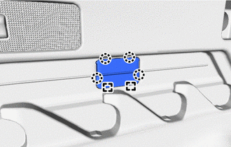
Attach the 2 guides and 4 claws to install the deck trim service hole cover.
62332C
40.INSTALL REAR DOOR OPENING TRIM WEATHERSTRIP LH
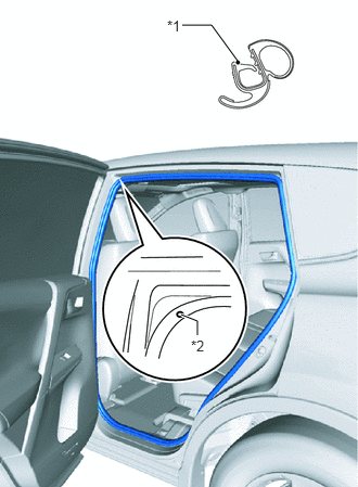
| *1 | Paint Mark |
| *2 | Mark Position |
Align the paint mark on the rear door opening trim weatherstrip LH with the mark position on the vehicle and install the rear door opening trim weatherstrip LH as shown in the illustration.
62331C
41.INSTALL REAR DOOR OPENING TRIM WEATHERSTRIP RH
- HINT:
-
Use the same procedure described for the LH side.
67918E
42.INSTALL REAR DOOR SCUFF PLATE LH
Attach the 6 clips and 2 claws to install the rear door scuff plate LH.
67917C
43.INSTALL REAR DOOR SCUFF PLATE RH
- HINT:
-
Use the same procedure described for the LH side.
62312B
44.INSTALL FRONT DOOR OPENING TRIM WEATHERSTRIP LH
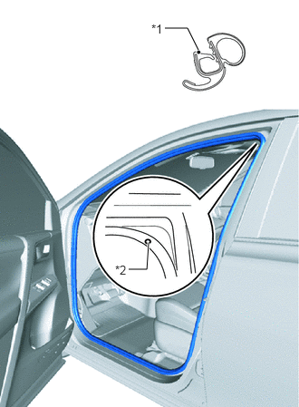
| *1 | Paint Mark |
| *2 | Mark Position |
Align the paint mark on the front door opening trim weatherstrip LH with the mark position on the vehicle and install the front door opening trim weatherstrip LH as shown in the illustration.
62311B
45.INSTALL FRONT DOOR OPENING TRIM WEATHERSTRIP RH
- HINT:
-
Use the same procedure described for the LH side.
67914B
46.INSTALL FRONT DOOR SCUFF PLATE LH
Attach the 2 clips and 8 claws to install the front door scuff plate LH.
67913B
47.INSTALL FRONT DOOR SCUFF PLATE RH
- HINT:
-
Use the same procedure described for the LH side.
48.INSTALL REAR SEAT ASSEMBLY
for LH Side:
Click hereVehicle Interior>SEAT>REAR SEAT ASSEMBLY(for LH Side)>INSTALLATION
for RH Side:
Click hereVehicle Interior>SEAT>REAR SEAT ASSEMBLY(for RH Side)>INSTALLATION
58577E
49.INSTALL REAR NO. 1 FLOOR MAT SUPPORT SIDE PLATE
Attach the 4 clips to install the rear No. 1 floor mat support side plate together with the rear No. 1 floor board.
Install the 4 screws.
Close the No. 1 rear floor board.
58386
50.INSTALL REAR FLOOR FINISH PLATE (w/o Spare Tire, for Compact Spare Tire)
Attach the 2 guides, 4 clips and 2 claws to install the rear floor finish plate.
64716P
51.INSTALL REAR DECK TRIM COVER (for Full Size Spare Tire)
Attach the 4 clips and 4 claws to install the rear deck trim cover.
58417H
52.INSTALL NO. 3 REAR FLOOR BOARD
for Compact Spare Tire:
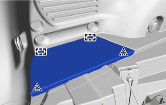
Attach the 2 guides and 2 clips to install the No. 3 rear floor board.
for Full Size Spare Tire:
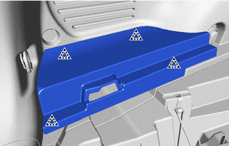
Attach the 4 clips to install the No. 3 rear floor board.
58416K
53.INSTALL NO. 2 REAR FLOOR BOARD
- HINT:
-
Use the same procedure described for the No. 3 rear floor board side.
64997
54.INSTALL DECK FLOOR BOX LH
Attach the 4 claws to install the deck floor box LH.
Install the 3 clips.
58410B
55.INSTALL DECK BOARD ASSEMBLY
Install the deck board assembly.
64910N
56.INSTALL TONNEAU COVER ASSEMBLY (w/ Tonneau Cover)
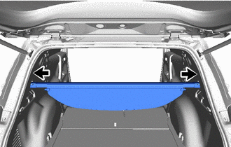
Attach the 2 locks to install the tonneau cover assembly.
64309A
57.INSTALL PACKAGE TRAY TRIM POCKET SUB-ASSEMBLY (w/ Partition Net)
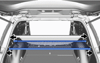
Attach the 4 locks to install the package tray trim pocket sub-assembly.
58.CONNECT CABLE TO NEGATIVE BATTERY TERMINAL
- NOTICE:
-
When disconnecting the cable, some systems need to be initialized after the cable is reconnected.
-
Click hereGeneral>INTRODUCTION>REPAIR INSTRUCTION>INITIALIZATION
59.CHECK SRS WARNING LIGHT