INTERIOR PANELS / TRIM INSTRUMENT PANEL SAFETY PAD DISASSEMBLY
CAUTION / NOTICE / HINT
- HINT:
- ·
Use the same procedure for RHD and LHD vehicles.
·The procedure listed below is for LHD vehicles.
PROCEDURE

 55950G
1.REMOVE DEFROSTER NOZZLE ASSEMBLY
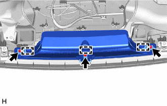

|
Screw <A> |
Remove the 3 screws <A>.
Detach the guide and remove the defroster nozzle assembly.
55084E
2.REMOVE NO. 1 HEATER TO REGISTER DUCT SUB-ASSEMBLY
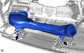
|
|
Screw <A> |
Remove the 2 screws <A>.
Detach the guide and remove the No. 1 heater to register duct sub-assembly.
55971C
3.REMOVE NO. 1 SIDE DEFROSTER NOZZLE DUCT
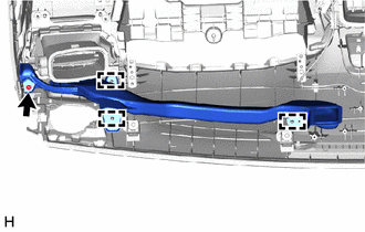
|
|
Screw <A> |
Remove the screw <A>.
Detach the guide and remove the No. 1 side defroster nozzle duct.
55650
4.REMOVE NO. 1 INSTRUMENT PANEL REGISTER ASSEMBLY
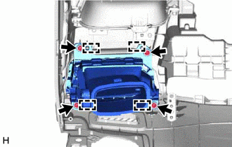
|
|
Screw <A> |
Remove the 4 screws <A>.
Detach the guide and remove the No. 1 instrument panel register assembly.
55961B
5.REMOVE NO. 1 SIDE DEFROSTER NOZZLE
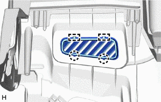
Detach the claw and guide and remove the No. 1 side defroster nozzle.
55086
6.REMOVE NO. 3 HEATER TO REGISTER DUCT SUB-ASSEMBLY
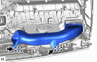
|
|
Screw <A> |
Remove the 2 screws <A>.
Detach the guide and remove the No. 3 heater to register duct sub-assembly.
55972C
7.REMOVE NO. 2 SIDE DEFROSTER NOZZLE DUCT
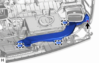
|
|
Screw <A> |
Remove the screw <A>.
Detach the guide and remove the No. 2 side defroster nozzle duct.
55660
8.REMOVE NO. 2 INSTRUMENT PANEL REGISTER ASSEMBLY
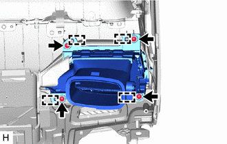
|
|
Screw <A> |
Remove the 4 screws <A>.
Detach the guide and remove the No. 2 instrument panel register assembly.
55962D
9.REMOVE NO. 2 SIDE DEFROSTER NOZZLE
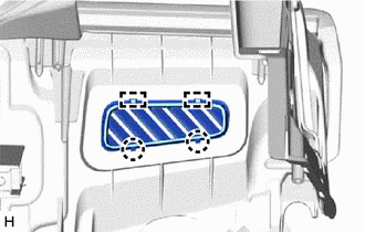
Detach the claw and guide and remove the No. 2 side defroster nozzle.
73960A
10.REMOVE INSTRUMENT PANEL PASSENGER AIRBAG ASSEMBLY
11.REMOVE NAVIGATION ANTENNA ASSEMBLY WITH BRACKET (w/ Navigation Antenna)
86681E
12.REMOVE ANTENNA DIVIDER (w/ Antenna Divider)
86101
13.REMOVE ANTENNA CORD SUB-ASSEMBLY (for LHD)
86101
14.REMOVE ANTENNA CORD SUB-ASSEMBLY (for RHD)
86842
15.REMOVE NO. 1 NAVIGATION WIRE (for LHD, w/ Navigation System)
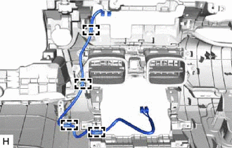
for Type A:
Detach the clamp and remove the No. 1 navigation wire.
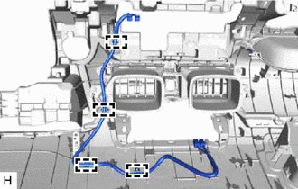
for Type B:
Detach the clamp and remove the No. 1 navigation wire.
86842
16.REMOVE NO. 1 NAVIGATION WIRE (for RHD, w/ Navigation System)
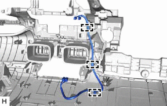
Detach the clamp and remove the No. 1 navigation wire.
55670A
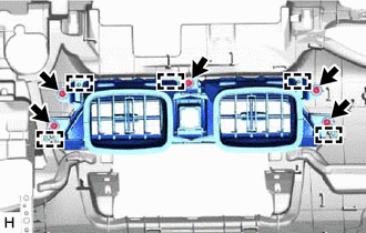
17.REMOVE CENTER INSTRUMENT PANEL REGISTER ASSEMBLY
|
|
Screw <A> |
Remove the 5 screws <A>.
Detach the guide and remove the center instrument panel register assembly.
55042B
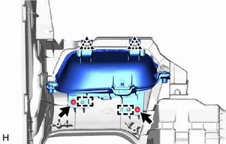
18.REMOVE NO. 2 INSTRUMENT PANEL BOX DOOR SUB-ASSEMBLY
|
|
Screw <A> |
Remove the 2 screws <A>.
Detach the clip and guide and remove the No. 2 instrument panel box door sub-assembly.
55041B
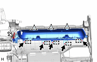
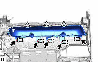
19.REMOVE NO. 1 INSTRUMENT PANEL BOX DOOR SUB-ASSEMBLY
w/ Interior Illumination:
|
|
Screw <A> |

|
Connector |
Disconnect the connector.
Remove the 5 screws <A>.
Detach the clip and guide and remove the No. 1 instrument panel box door sub-assembly.
w/o Interior Illumination:
|
|
Screw <A> |
Remove the 5 screws <A>.
Detach the clip and guide and remove the No. 1 instrument panel box door sub-assembly.
89120A
20.REMOVE AUTOMATIC LIGHT CONTROL SENSOR
82143
21.REMOVE NO. 3 INSTRUMENT PANEL WIRE
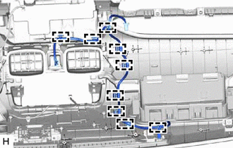
Detach the clamp and remove the No. 3 instrument panel wire.
55981
22.REMOVE NO. 1 DEFROSTER NOZZLE GARNISH
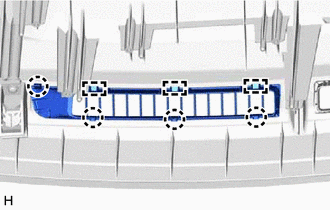
Detach the claw and guide and remove the No. 1 defroster nozzle garnish.
55982
23.REMOVE NO. 2 DEFROSTER NOZZLE GARNISH
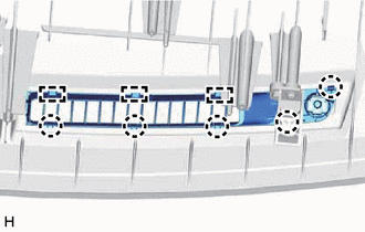
Detach the claw and guide and remove the No. 2 defroster nozzle garnish.
55315A
24.REMOVE NO. 1 INSTRUMENT PANEL SPACER (for Type A)
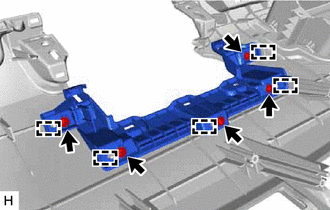
|
|
Screw <A> |
Remove the 5 screws <A>.
Detach the guide and remove the No. 1 instrument panel spacer.
55328
25.REMOVE NO. 1 INSTRUMENT PANEL PIN
Remove the 4 screws <A>.
Detach the guide and remove the 4 No. 1 instrument panel pins.
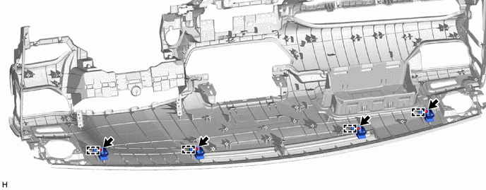
|
|
Screw <A> | - | - |
83107A
26.REMOVE NO. 1 METER BRACKET SUB-ASSEMBLY
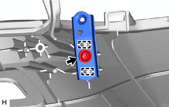
|
|
Screw <A> |
for LH Side:
Remove the screw <A>.
Detach the guide and remove the No. 1 meter bracket sub-assembly.
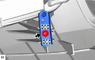
|
|
Screw <A> |
for RH Side:
Remove the screw <A>.
Detach the guide and remove the No. 1 meter bracket sub-assembly.
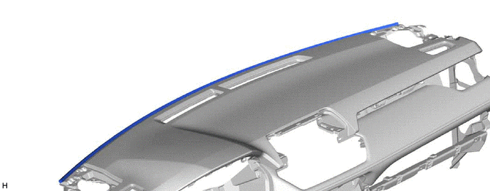
55349A
27.REMOVE INSTRUMENT PANEL CUSHION
Remove the instrument panel cushion.
69056A
28.REMOVE GLOVE COMPARTMENT LOCK CYLINDER (w/ Lock Cylinder)
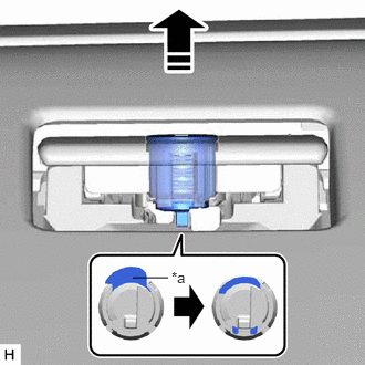
| *a | Stopper |

|
Remove in this Direction |
Push the stopper to release the lock, and then push the glove compartment door lock cylinder and remove it from the glove compartment door assembly.
55557A
29.REMOVE GLOVE COMPARTMENT DOOR CHECK CUSHION
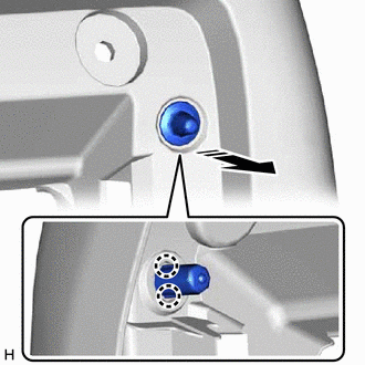
|
|
Remove in this Direction |
Detach the claw and remove the glove compartment door check cushion.
- HINT:
-
Use the same procedure to remove the glove compartment door check cushion on the other side.
55548A
30.REMOVE INSTRUMENT PANEL HOLE COVER (for RHD)
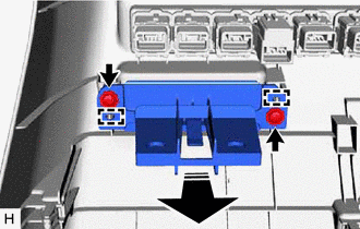
|
|
Screw <A> |
|
|
Remove in this Direction |
Remove the 2 screws <A>.
Detach the guide and remove the instrument panel hole cover.
55539D
31.REMOVE SPARE SWITCH HOLE COVER (w/o Light Control Rheostat)
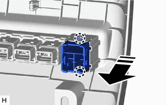
|
|
Remove in this Direction |
Detach the claw and remove the spare switch hole cover.