Home › Audio / Visual / Telematics › AUDIO / VIDEO › AUDIO AND VISUAL SYSTEM (for Radio Receiver Type)
RM3620E _56 Audio / Visual / Telematics _076047 AUDIO / VIDEO _0370279 AUDIO AND VISUAL SYSTEM(for Radio Receiver Type) J

AUDIO / VIDEO  AUDIO AND VISUAL SYSTEM(for Radio Receiver Type)  Steering Pad Switch Circuit  


DESCRIPTION

This circuit sends an operation signal from the steering pad switch assembly to the radio receiver assembly.

If there is an open in the circuit, the audio system cannot be operated using the steering pad switch assembly.

If there is a short in the circuit, the same condition as when a switch is continuously depressed occurs.

Therefore, the radio receiver assembly cannot be operated using the steering pad switch assembly, and also the radio receiver assembly itself cannot function.

WIRING DIAGRAM
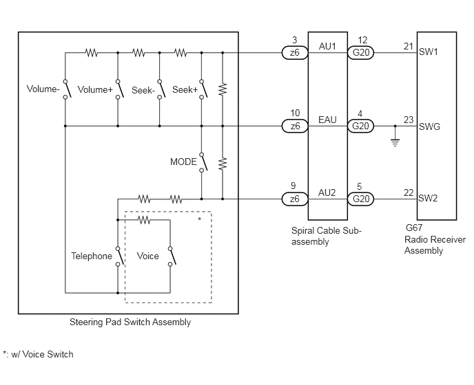
E412456E01
1.052,4.792 5.333,4.99 4.281,0.198 10 false Steering Pad Switch Assembly 4.406,3.406 5.542,3.969 1.135,0.563 10 false Spiral Cable Sub-assembly 6.115,3.542 7.115,4.01 1,0.469 10 false Radio Receiver Assembly 6.135,3.365 6.594,3.563 0.458,0.198 10 false G67 2.573,2.365 3.344,2.771 0.771,0.406 10 false MODE 1.073,3.792 2.198,4.042 1.125,0.25 10 false Telephone 0.406,1.26 1.479,1.458 1.073,0.198 10 false Volume- 1.177,1.271 2.25,1.469 1.073,0.198 10 false Volume+ 1.99,1.281 3.063,1.479 1.073,0.198 10 false Seek- 2.604,1.271 3.677,1.469 1.073,0.198 10 false Seek+ 4.813,2.833 5.281,3.042 0.469,0.208 10 false AU2 4.813,1.729 5.281,1.938 0.469,0.208 10 false EAU 4.823,0.615 5.292,0.823 0.469,0.208 10 false AU1 4.385,2.927 4.698,3.125 0.313,0.198 10 false z6 4.396,1.823 4.708,2.021 0.313,0.198 10 false z6 4.385,0.708 4.698,0.906 0.313,0.198 10 false z6 5.333,2.927 5.792,3.125 0.458,0.198 10 false G20 5.323,1.823 5.781,2.021 0.458,0.198 10 false G20 5.333,0.708 5.792,0.906 0.458,0.198 10 false G20 4.417,0.521 4.729,0.719 0.313,0.198 10 false 3 4.385,1.625 4.698,1.823 0.313,0.198 10 false 10 4.396,2.729 4.708,2.927 0.313,0.198 10 false 9 5.406,0.521 5.719,0.719 0.313,0.198 10 false 12 5.396,2.74 5.708,2.938 0.313,0.198 10 false 5 5.406,1.635 5.719,1.833 0.313,0.198 10 false 4 6.104,2.833 6.417,3.031 0.313,0.198 10 false 22 6.104,1.729 6.417,1.927 0.313,0.198 10 false 23 6.104,0.615 6.417,0.813 0.313,0.198 10 false 21 6.333,0.698 6.802,0.906 0.469,0.208 10 false SW1 6.333,1.833 6.802,2.042 0.469,0.208 10 false SWG 6.323,2.917 6.792,3.125 0.469,0.208 10 false SW2 2.073,3.792 2.604,4.01 0.531,0.219 10 false Voice 2.99,3.26 3.302,3.458 0.313,0.198 10 false * 0.042,5.281 1.646,5.49 1.604,0.208 10 false *: w/ Voice Switch

CAUTION / NOTICE / HINT

NOTICE:

The vehicle is equipped with a Supplemental Restraint System (SRS) which includes components such as airbags. Before servicing (including removal or installation of parts), be sure to read the precaution for Supplemental Restraint System.

Click hereVehicle Interior>SUPPLEMENTAL RESTRAINT SYSTEMS>AIRBAG SYSTEM (w/o Occupant Classification System)>HOW TO PROCEED WITH TROUBLESHOOTING


HINT:

Voice switch availability depends on the vehicle. Even if the voice switch is available the function does not operate.


PROCEDURE

1.INSPECT STEERING PAD SWITCH ASSEMBLY
a.

Remove the steering pad switch assembly.

Click hereSteering>STEERING COLUMN>STEERING PAD SWITCH>REMOVAL


b.

Inspect the steering pad switch assembly.

Click hereSteering>STEERING COLUMN>STEERING PAD SWITCH>INSPECTION


Result:
Proceed to
OK
NG


OK

2.INSPECT SPIRAL CABLE SUB-ASSEMBLY

NG

REPLACE STEERING PAD SWITCH ASSEMBLY

2.INSPECT SPIRAL CABLE SUB-ASSEMBLY
a.

Remove the spiral cable sub-assembly.

Click hereVehicle Interior>SUPPLEMENTAL RESTRAINT SYSTEMS>SPIRAL CABLE>REMOVAL


b.

Inspect the spiral cable sub-assembly.

Click hereVehicle Interior>SUPPLEMENTAL RESTRAINT SYSTEMS>SPIRAL CABLE>INSPECTION


Result:
Proceed to
OK
NG


OK

3.CHECK HARNESS AND CONNECTOR (RADIO RECEIVER ASSEMBLY - SPIRAL CABLE SUB-ASSEMBLY)

NG

REPLACE SPIRAL WITH SENSOR CABLE SUB-ASSEMBLY

3.CHECK HARNESS AND CONNECTOR (RADIO RECEIVER ASSEMBLY - SPIRAL CABLE SUB-ASSEMBLY)
a.

Disconnect the G67 radio receiver assembly connector.


b.

Disconnect the G20 spiral cable sub-assembly connector.


c.

Measure the resistance according to the value(s) in the table below.

Standard Resistance:
Tester Connection Condition Specified Condition
G67-21 (SW1) - G20-12 (AU1) Always Below 1 Ω
G67-22 (SW2) - G20-5 (AU2) Always Below 1 Ω
G67-23 (SWG) - G20-4 (EAU) Always Below 1 Ω
G67-21 (SW1) - Body ground Always 10 kΩ or higher
G67-22 (SW2) - Body ground Always 10 kΩ or higher


Result:
Proceed to
OK
NG


OK

NG

REPAIR OR REPLACE HARNESS OR CONNECTOR