AUDIO / VIDEO AUDIO AND VISUAL SYSTEM(for Radio Receiver Type) Clock Communication Error
WIRING DIAGRAM
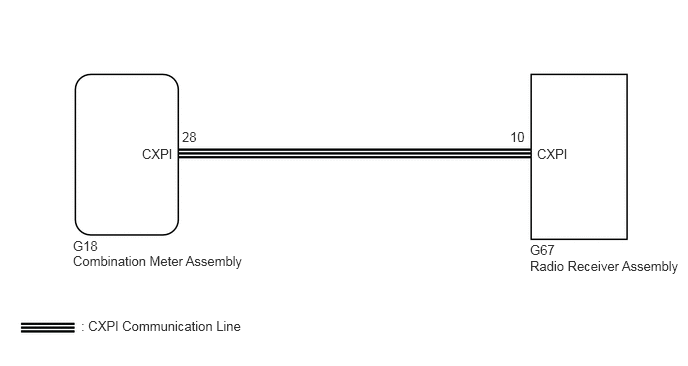
PROCEDURE
Check if the clock function in the combination meter assembly operates normally.
- OK:
The clock function in the combination meter assembly operates normally.
- Result:
Proceed to OK NG
OK
NG
Click hereVehicle Interior>METER / GAUGE / DISPLAY>METER / GAUGE SYSTEM>HOW TO PROCEED WITH TROUBLESHOOTING
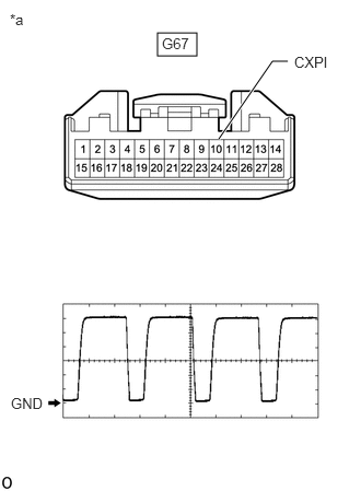
| *a | Front view of wire harness connector
(to Radio Receiver Assembly) |
Check the output waveform.
Disconnect the radio receiver assembly connector.
Connect an oscilloscope to terminal 10 (CXPI) and body ground.
Turn the ignition switch to ON.
Check the signal waveform according to the condition(s) in the table below.
| Item | Condition |
|---|---|
| Measurement terminal | G67-10 (CXPI) - Body ground |
| Tool setting | 2 V/DIV., 20 μs./DIV. |
| Vehicle condition | Ignition switch ON |
- OK:
The waveform is similar to that shown in the illustration.
- HINT:
-
The waveform varies depending on the CXPI communication signal.
- Result:
Proceed to OK NG
OK
NG
Disconnect the G18 combination meter assembly connector.
Disconnect the G67 radio receiver assembly connector.
Measure the resistance according to the value(s) in the table below.
- Standard Resistance:
Tester Connection Condition Specified Condition G18-28 (CXPI) - G67-10 (CXPI) Always Below 1 Ω G18-18 (CXPI) - Body ground Always 10 kΩ or higher
- Result:
Proceed to OK NG
OK
NG