CRUISE CONTROL LANE CONTROL SYSTEM Steering Pad Switch Circuit
DESCRIPTION
The forward recognition camera receives the LTA/LDA main switch on/off signal from the steering pad switch assembly.
WIRING DIAGRAM
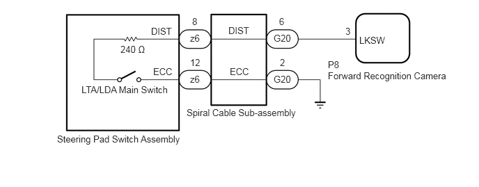
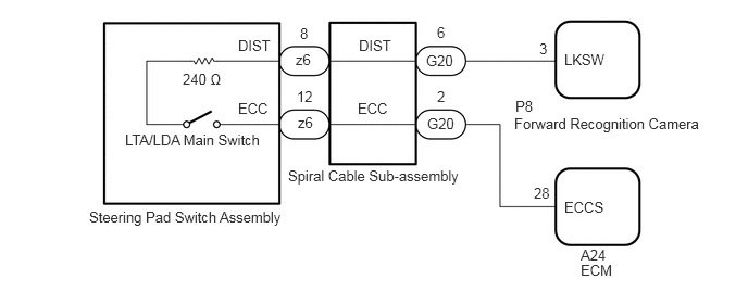
CAUTION / NOTICE / HINT
- NOTICE:
-
During the steering pad switch assembly check, check the precautions for the airbag system since the horn button assembly is removed during servicing (installation/removal of parts, checks, replacement, etc.).
for HV Model with Occupant Classification System:Vehicle Interior>SUPPLEMENTAL RESTRAINT SYSTEMS>AIRBAG SYSTEM (for HV Model with Occupant Classification System)>PRECAUTION
for Gasoline Model with Occupant Classification System:Vehicle Interior>SUPPLEMENTAL RESTRAINT SYSTEMS>AIRBAG SYSTEM (for Gasoline Model with Occupant Classification System)>PRECAUTION
w/o Occupant Classification System:Vehicle Interior>SUPPLEMENTAL RESTRAINT SYSTEMS>AIRBAG SYSTEM (w/o Occupant Classification System)>PRECAUTION
PROCEDURE
Remove the steering pad switch assembly.
Click hereSteering>STEERING COLUMN>STEERING PAD SWITCH>REMOVAL
Inspect the steering pad switch assembly.
Click hereSteering>STEERING COLUMN>STEERING PAD SWITCH>INSPECTION
- Result:
Proceed to OK NG
OK
NG
Remove the spiral cable sub-assembly.
Click hereVehicle Interior>SUPPLEMENTAL RESTRAINT SYSTEMS>SPIRAL CABLE>REMOVAL
Inspect the spiral cable sub-assembly.
Click hereVehicle Interior>SUPPLEMENTAL RESTRAINT SYSTEMS>SPIRAL CABLE>INSPECTION
- Result:
Proceed to OK NG
OK
NG
Disconnect the G20 spiral cable sub-assembly connector.
Disconnect the P8 forward recognition camera connector.
Measure the resistance according to the value(s) in the table below.
- Standard Resistance:
Tester Connection Condition Specified Condition G20-6 (DIST) - P8-3 (LKSW) Always Below 1 Ω
Connect the G20 spiral cable sub-assembly connector.
Connect the P8 forward recognition camera connector.
- Result:
Result Proceed to OK (for HV Model) A OK (for Gasoline Model) B NG C
A
B
C
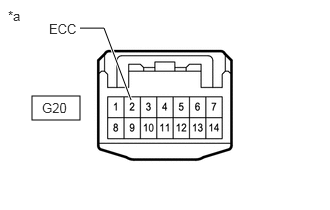
| *a | Front view of wire harness connector
(to Spiral Cable Sub-assembly) |
Disconnect the spiral cable sub-assembly connector.
Measure the resistance according to the value(s) in the table below.
- Standard Resistance:
Tester Connection Condition Specified Condition G20-2 (ECC) - Body ground Always Below 1 Ω
Connect the spiral cable sub-assembly connector.
- Result:
Proceed to OK NG
OK
NG
Disconnect the G20 spiral cable sub-assembly connector.
Disconnect the A24 ECM connector.
Measure the resistance according to the value(s) in the table below.
- Standard Resistance:
Tester Connection Condition Specified Condition G20-2 (ECC) - A24-28 (ECCS) Always Below 1 Ω
Connect the G20 spiral cable sub-assembly connector.
Connect the A24 ECM connector.
- Result:
Proceed to OK NG
OK
NG