A25A-FKS STARTING STARTER(w/ Stop And Start System) INSTALLATION
PROCEDURE

 28100
1.INSTALL STARTER ASSEMBLY
Install the starter assembly to the cylinder block sub-assembly with the 2 bolts.
- Torque:
- 46 N*m (469 kgf*cm, 34 ft.*lbf)
Connect the No. 2 engine wire to terminal 30 with the nut.
- Torque:
- 9.8 N*m (100 kgf*cm, 87 in.*lbf)
Close the terminal cap.
Connect the starter assembly connector.
Install the No. 1 radiator bracket to the front engine mounting with the bolt.
- Torque:
- 19 N*m (194 kgf*cm, 14 ft.*lbf)
Attach the 3 clamps to install the radiator hose, vacuum hoses and No. 2 engine wire to the No. 1 radiator bracket.
Attach the 2 clamps to install the engine wire and No. 2 engine wire to the automatic transaxle assembly.
Attach the clamp to install the radiator hose to the fan shroud assembly.
Install the engine wire to the vehicle body with the bolt.
- Torque:
- 8.0 N*m (82 kgf*cm, 71 in.*lbf)
11363A
2.INSTALL FLYWHEEL HOUSING SIDE COVER
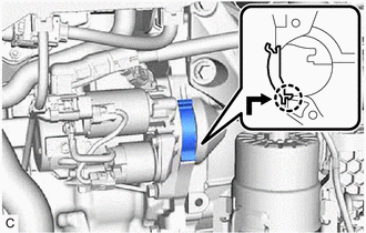
Align the protrusion with the cylinder block sub-assembly and attach the claw as shown in the illustration to install the flywheel housing side cover.
- NOTICE:
- ·
Make sure the claw makes a click sound, indicating that it fits tightly.
·Replace the flywheel housing side cover with a new one if the claw does not fit tightly or is deformed.
3.INSTALL AIR CLEANER ASSEMBLY WITH AIR CLEANER HOSE
17750A
4.INSTALL INLET AIR CLEANER ASSEMBLY
12601B
5.INSTALL NO. 1 ENGINE COVER SUB-ASSEMBLY
12361A
6.INSTALL FRONT ENGINE MOUNTING INSULATOR
7.CONNECT CABLE TO NEGATIVE BATTERY TERMINAL