POWER OUTLETS (INT) WIRELESS CHARGER ASSEMBLY INSTALLATION
CAUTION / NOTICE / HINT
- HINT:
- ·
Use the same procedure for RHD and LHD vehicles.
·The procedure listed below is for LHD vehicles.
PROCEDURE

 85535B
1.INSTALL NO. 1 POWER OUTLET SOCKET COVER
85530
2.INSTALL NO. 1 POWER OUTLET SOCKET ASSEMBLY
55524A
3.INSTALL SWITCH BASE HOLE COVER (w/o Radio Receiver)
86190C
4.INSTALL NO. 1 STEREO JACK ADAPTER ASSEMBLY (w/ Radio Receiver)
861C0
5.INSTALL MOBILE WIRELESS CHARGER CRADLE ASSEMBLY
w/ Radio Receiver:
Connect the 3 connectors and attach the clamp.
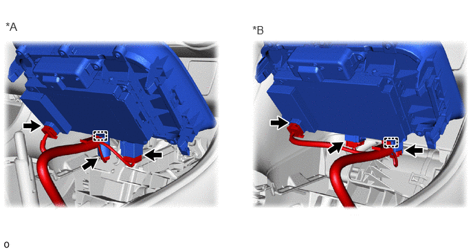
| *A | except Manual Transaxle | *B | for Manual Transaxle |
w/o Radio Receiver:
Connect the 2 connectors and attach the clamp.
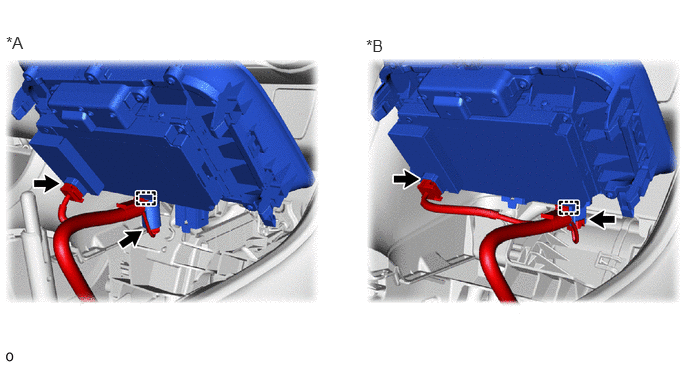
| *A | except Manual Transaxle | *B | for Manual Transaxle |
Attach the guide in the direction indicated by the arrow (1) shown in the illustration.
Rotate in the direction indicated by the arrow (2) shown in the illustration to attach the clip and install the mobile wireless charger cradle assembly.
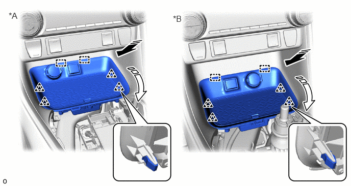
| *A | except Manual Transaxle | *B | for Manual Transaxle |

|
Install in this Direction (1) | 
|
Install in this Direction (2) |
58804A
6.INSTALL UPPER CONSOLE PANEL SUB-ASSEMBLY
33504F
7.INSTALL SHIFT LEVER KNOB SUB-ASSEMBLY (for Manual Transaxle)
33504F
8.INSTALL SHIFT LEVER KNOB SUB-ASSEMBLY (except Manual Transaxle)
for Automatic Transaxle:
UB80E:
for CVT:
K120:
Click hereDrivetrain>K120 (MULTIDRIVE / CVT)>SHIFT LEVER KNOB>INSTALLATION
K120F:
Click hereDrivetrain>K120F (MULTIDRIVE / CVT)>SHIFT LEVER KNOB>INSTALLATION
for HV Model: