A25A-FXS COOLING FLOW SHUTTING VALVE REMOVAL
CAUTION / NOTICE / HINT
The necessary procedures (adjustment, calibration, initialization, or registration) that must be performed after parts are removed and installed, or replaced during flow shutting valve (water by-pass hose assembly) removal/installation are shown below.
| Replaced Part or Performed Procedure | Necessary Procedures | Effect/Inoperative Function when Necessary Procedure not Performed | Link |
|---|---|---|---|
|
*: When performing learning using the GTS. Click here( |
|||
| Auxiliary battery terminal is disconnected/reconnected | Perform steering sensor zero point calibration | Lane control system | ( ) |
| Parking support brake system (for HV model)* | |||
| Pre-collision system | |||
| Memorize steering angle neutral point | Parking assist monitor system | ()
|
|
| Panoramic view monitor system (for HV model) | ()
|
||
| Reset back door close position | Power back door system (for HV model) | ()
|
|
| Power back door initialization | Power door lock control system | ()
|
|
| Replacement of inverter with converter assembly | Resolver learning | ·
DTCs are stored ·
Slight vibration at a vehicle speed of 5 km/h (3 mph) or less ·
Shock or vibration during acceleration |
for 2WD with NICKEL METAL HYDRIDE BATTERY:
( )
for 4WD/AWD with NICKEL METAL HYDRIDE BATTERY: ( )
for 2WD with LITHIUM-ION BATTERY: ( )
for 4WD/AWD with LITHIUM-ION BATTERY: ( )
|
| Replacement of ECM | w/ Canister Pump Module:
Perform Vehicle Identification Number (VIN) registration |
DTC P063051 is output | ()
|
w/o Canister Pump Module:
Perform Vehicle Identification Number (VIN) or frame number registration |
()
|
||
| Grille shutter switch specification infomation | Vehicle control history (RoB) [X260E] is stored | w/ Canister Pump Module:()
w/o Canister Pump Module:( )
|
|
- NOTICE:
-
After the power switch is turned off, the navigation system requires approximately a minute to record various types of memory and settings. As a result, after turning the power switch off, wait a minute or more before disconnecting the cable from the negative (-) auxiliary battery terminal.
PROCEDURE

 G9200
1.REMOVE INVERTER WITH CONVERTER ASSEMBLY
2.DRAIN ENGINE COOLANT (for Engine)
16260
3.REMOVE FLOW SHUTTING VALVE (WATER BY-PASS HOSE ASSEMBLY)
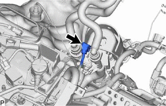
Disconnect the flow shutting valve (water by-pass hose assembly) connector.
Disconnect the outlet heater water hose connector from the No. 2 water by-pass pipe sub-assembly.
- NOTICE:
-
Remove any foreign matter on the No. 2 water by-pass pipe sub-assembly and outlet heater water hose connector before performing this work.
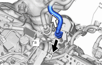
| *a | Retainer |

|
Pull out |

|
Pull off |
Pull out the retainer to detach the lock claws and pull off the outlet heater water hose connector.
Check that there is no foreign matter on the sealing surfaces of the disconnected water lines. Clean them if necessary.
Cover the disconnected No. 2 water by-pass pipe sub-assembly and outlet heater water hose connector with plastic bags to prevent damage and contamination.
Disconnect the inlet heater water hose connector from the flow shutting valve (water by-pass hose assembly).
- NOTICE:
-
Remove any foreign matter on the flow shutting valve (water by-pass hose assembly) and inlet heater water hose connector before performing this work.
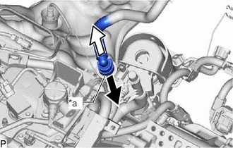
| *a | Retainer |
|
|
Pull out |
|
|
Pull off |
Pull out the retainer to detach the lock claws and pull off the inlet heater water hose connector.
Check that there is no foreign matter on the sealing surfaces of the disconnected water lines. Clean them if necessary.
Cover the disconnected inlet heater water hose connector with a plastic bag to prevent damage and contamination.
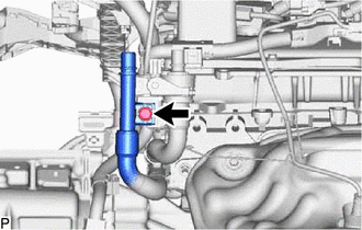
Remove the bolt to disconnect the No. 2 water by-pass pipe sub-assembly.
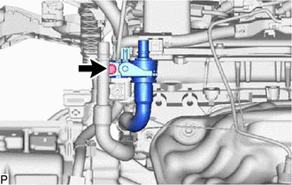
Remove the bolt to disconnect the flow shutting valve (water by-pass hose assembly).
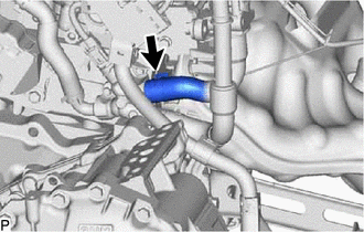
Slide the clip and disconnect the flow shutting valve (water by-pass hose assembly) from the water by-pass outlet sub-assembly.
- HINT:
-
Use a container to catch any engine coolant which flows out of the flow shutting valve (water by-pass hose assembly) and water by-pass outlet sub-assembly.