K120 MULTIDRIVE / CVT VALVE BODY ASSEMBLY REMOVAL
CAUTION / NOTICE / HINT
The necessary procedures (adjustment, calibration, initialization, or registration) that must be performed after parts are removed, installed, or replaced during the transmission valve body assembly removal/installation are shown below.
| Replacement Part or Procedure | Necessary Procedure | Effect/Inoperative when not Performed | Link |
|---|---|---|---|
|
*: When performing learning using the GTS. Click here( |
|||
| Battery terminal is disconnected/reconnected | Drive the vehicle until stop and start control is permitted (approximately 5 to 60 minutes) | Stop and start system | ( ) |
| Perform steering sensor zero point calibration | Lane control system | ()
|
|
| Parking support brake system (for Gasoline model)* | |||
| Pre-collision system | |||
| Memorize steering angle neutral point | Parking assist monitor system | ()
|
|
| Panoramic view monitor system (for Gasoline model) | ()
|
||
| Reset back door close position | Power back door system (for Gasoline model) | ()
|
|
| Power back door initialization | Power door lock control system | ()
|
|
| Transmission valve body assembly | ·
Reset transaxle compensation code ·
Perform reset memory ·
Deceleration sensor zero point calibration ·
CVT oil pressure calibration ·
Perform road test to allow TCM to learn |
·
Large shift shock ·
Deterioration of fuel efficiency |
for Initialization:()
for Registration:( )
|
| CVT fluid | ATF thermal degradation estimate reset | The value of the Data List item "ATF Thermal Degradation Estimate" is not estimated correctly | ()
|
| Air bleed oil pump with motor assembly (w/ Stop and Start System) | Stop and start system | ()
|
|
- NOTICE:
-
After the ignition switch is turned off, the navigation system requires approximately a minute to record various types of memory and settings. As a result, after turning the ignition switch off, wait a minute or more before disconnecting the cable from the negative (-) battery terminal.
- HINT:
-
Shift shock may increase after replacing the transmission valve body assembly. In this case, shift shock will reduce as the vehicle in driven.
PROCEDURE

 35015Y
1.REMOVE TRANSAXLE SIDE COVER SUB-ASSEMBLY
35410J
2.REMOVE TRANSMISSION VALVE BODY ASSEMBLY
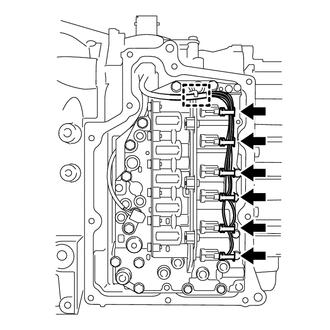
Detach the clamp to disconnect the transmission wire from the solenoid lock plate.
Disconnect the 6 solenoid valve connectors.
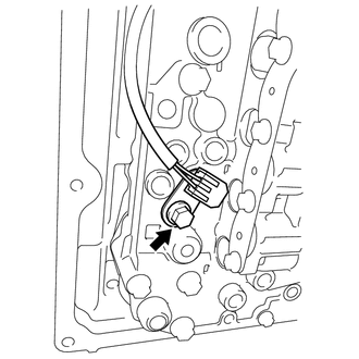
Remove the bolt and temperature sensor clamp from the transmission valve body assembly.
Disconnect the temperature sensor from the transmission valve body assembly.
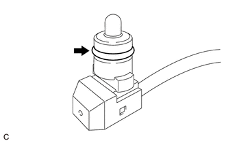
Remove the O-ring from the temperature sensor.
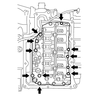
Remove the 11 bolts and transmission valve body assembly from the transaxle case sub-assembly.
- NOTICE:
-
Make sure the manual valve does not fall out when removing the transmission valve body assembly, as the manual valve is not secured to the transmission valve body assembly.
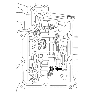
Remove the front oil pump cover gasket from the transaxle case sub-assembly.
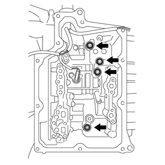
Remove the 4 transaxle case gaskets from the transaxle case sub-assembly.