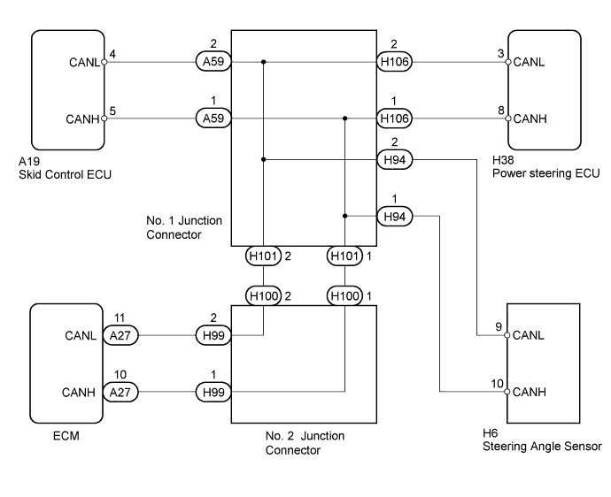
POWER STEERING SYSTEM > Power Steering ECU Communication Circuit |
| 1.CHECK CAN COMMUNICATION SYSTEM |
Check if the CAN communication system DTC is output (Click here).
| Result | Proceed to |
| DTC not output | A |
| DTC output | B |
|
| ||||
| A | |
 |
| 2.CHECK VEHICLE STABILITY CONTROL SYSTEM |
Check if the vehicle stability control system DTC is output (Click here).
| Result | Proceed to |
| DTC not output | A |
| DTC output | B |
|
| ||||
| A | |
|
| 3.CHECK SFI SYSTEM |
Check if the SFI system DTC is output
(Click here for 3UR-FE)
(Click here for 3UR-FBE)
(Click here for 2UZ-FE).
| Result | Proceed to |
| DTC not output | A |
| DTC output (3UR-FE) | B |
| DTC output (3UR-FBE) | C |
| DTC output (2UZ-FE) | D |
|
| ||||
|
| ||||
|
| ||||
| A | ||
 | ||
| ||
