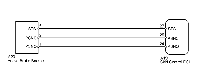
DTC C1267/28 Brake Pedal Load Sensing Switch |
| DTC Code | DTC Detection Condition | Trouble Area |
| C1267/28 | When one of following conditions is met:
|
|
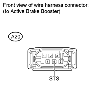
| 1.CHECK TERMINAL VOLTAGE (BOOSTER PEDAL MICRO SWITCH) |
 |
Disconnect A20 booster connector.
Turn the ignition switch to ON.
Measure the voltage according to the value(s) in the table below.
| Tester Connection | Switch Condition | Specified Condition |
| A20-5 (STS) - Body ground | Ignition switch ON | Approximately 12 V |
|
| ||||
| OK | |
 |
| 2.INSPECT BOOSTER PEDAL MICRO SWITCH |
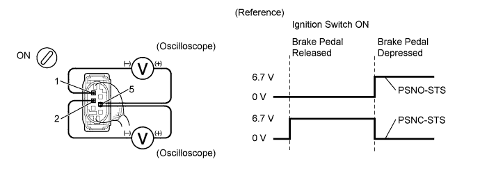
When using an oscilloscope:
Connect the oscilloscope between terminals 1 (PSNO) and 5 (STS), 2 (PSNC) and 5 (STS) of the brake booster with connector being connected.
Turn the ignition switch to ON.
Check the signal waveform while the brake pedal is depressed and released.
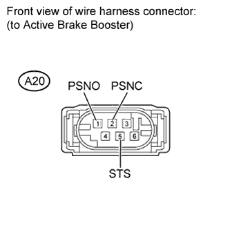 |
When not using an oscilloscope:
Disconnect the A20 booster connector.
Turn the ignition switch to ON.
Measure the voltage according to the value(s) in the table below.
| Tester Connection | Condition | Specified Condition |
| A20-2 (PSNC) - A20-5 (STS) | Brake pedal is depressed | 6 V |
| A20-1 (PSNO) - A20-5 (STS) | Brake pedal is released |
|
| ||||
| OK | |
|
| 3.CHECK HARNESS AND CONNECTOR (BOOSTER PEDAL MICRO SWITCH - SKID CONTROL ECU) |
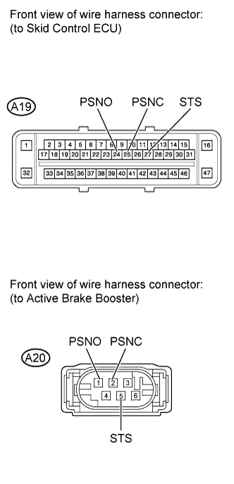 |
Confirm that the skid control ECU connector and brake booster connector are properly connected.
Disconnect the A19 ECU connector.
Disconnect the A20 booster connector.
Inspect both the connector case and the terminal for deformation and corrosion.
Measure the resistance according to the value(s) in the table below.
| Tester Connection | Condition | Specified Condition |
| A19-24 (PSNO) - A20-1 (PSNO) | Always | Below 1 Ω |
| A19-24 (PSNO) - Body ground | Always | 10 kΩ or higher |
| A19-25 (PSNC) - A20-2 (PSNC) | Always | Below 1 Ω |
| A19-25 (PSNC) - Body ground | Always | 10 kΩ or higher |
| A19-27 (STS) - A20-5 (STS) | Always | Below 1 Ω |
| A19-27 (STS) - Body ground | Always | 10 kΩ or higher |
|
| ||||
| OK | ||
 | ||
| ||

