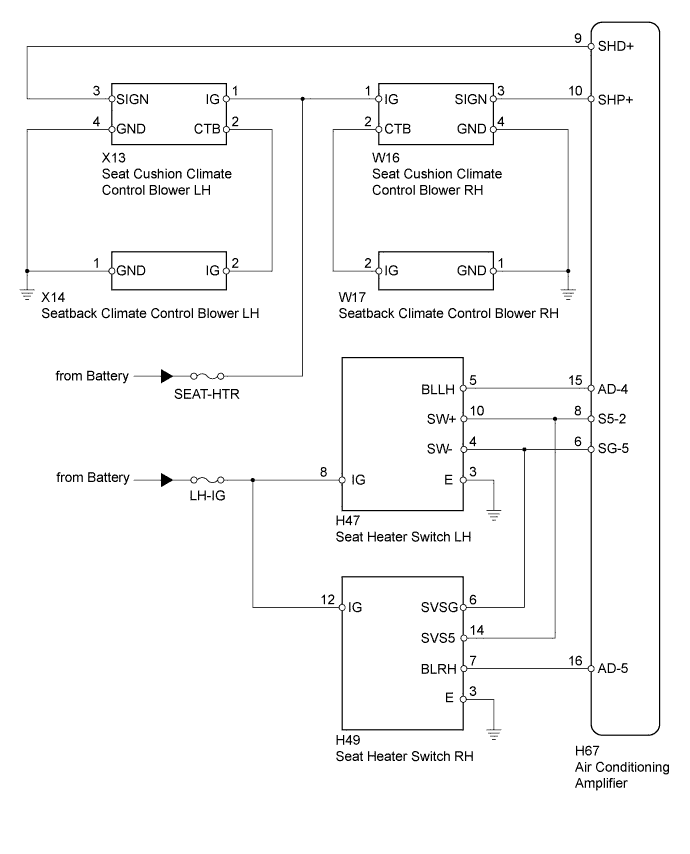
CLIMATE CONTROL SEAT SYSTEM > Climate Control Seat System does not Operate |
| 1.CHECK CLIMATE CONTROL SEAT SYSTEM OPERATION |
Check if the climate control seat system operates normally.
| Result | Proceed to |
| Climate control does not operate on both driver and passenger sides | A |
| Climate control does not operate on driver side | B |
| Climate control does not operate on front passenger side | C |
|
| ||||
|
| ||||
| A | |
 |
| 2.INSPECT FUSE (LH-IG, SEAT-HTR) |
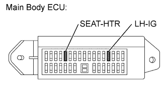 |
Remove the LH-IG and SEAT-HTR fuses from the main body ECU.
Measure the resistance according to the value(s) in the table below.
| Tester Connection | Condition | Specified Condition |
| LH-IG fuse | Always | Below 1 Ω |
| SEAT-HTR fuse | Always | Below 1 Ω |
|
| ||||
| OK | |
|
| 3.CHECK HARNESS AND CONNECTOR (SEAT HEATER SWITCH) |
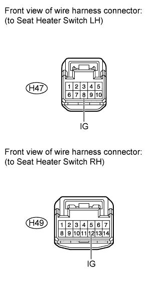 |
Disconnect the H47 and H49 switch connectors.
Measure the voltage according to the value(s) in the table below.
| Tester Connection | Switch Condition | Specified Condition |
| H47-8 (IG) - Body ground | Ignition switch ON | 11 to 14 V |
| H49-12 (IG) - Body ground | Ignition switch ON | 11 to 14 V |
|
| ||||
| OK | |
|
| 4.CHECK HARNESS AND CONNECTOR (SEAT CLIMATE CONTROL BLOWER - BATTERY AND BODY GROUND) |
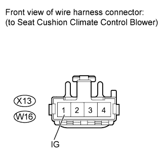 |
Disconnect the X13 and W16 blower connectors.
Measure the voltage according to the value(s) in the table below.
| Tester Connection | Switch Condition | Specified Condition |
| X13-1 (IG) - Body ground | Ignition switch ON | 11 to 14 V |
| W16-1 (IG) - Body ground | Ignition switch ON | 11 to 14 V |
|
| ||||
| OK | ||
 | ||
| ||
| 5.CHECK HARNESS AND CONNECTOR (SEAT CLIMATE CONTROL BLOWER LH - BATTERY AND BODY GROUND) |
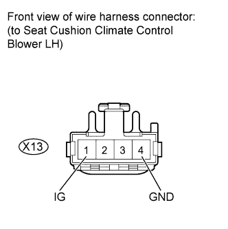 |
Disconnect the X13 blower connector.
Measure the voltage and resistance according to the value(s) in the table below.
| Tester Connection | Switch Condition | Specified Condition |
| X13-1 (IG) - Body ground | Ignition switch ON | 11 to 14 V |
| Tester Connection | Condition | Specified Condition |
| X13-4 (GND) - Body ground | Always | Below 1 Ω |
Reconnect the X13 blower connector.
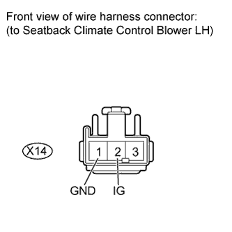 |
Disconnect the X14 blower connector.
Measure the voltage and resistance according to the value(s) in the table below.
| Tester Connection | Condition | Specified Condition |
| X14-1 (GND) - Body ground | Always | Below 1 Ω |
| Tester Connection | Condition | Specified Condition |
| X14-2 (IG) - Body ground | Ignition switch ON | 11 to 14 V |
|
| ||||
| OK | |
|
| 6.INSPECT SEAT CLIMATE CONTROL BLOWER LH |
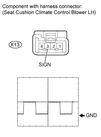 |
Check the input signal waveform.
Connect an oscilloscope to terminal X13-3 (SIGN) and body ground with the climate control blower connector still connected.
Check the signal waveform according to the condition(s) in the table below.
| Terminal No. (Symbol) | Tool setting | Condition |
| X13-3 (SIGN) - Body ground | 2 V/DIV., 500 μsec/DIV. | Ignition switch ON Seat heater switch blower side volume 3 |
| Result | Proceed to |
| NG | A |
| OK (Seat cushion blower side) | B |
| OK (Seatback blower side) | C |
|
| ||||
|
| ||||
| A | |
|
| 7.CHECK HARNESS AND CONNECTOR (AIR CONDITIONING AMPLIFIER - SEAT CLIMATE CONTROL BLOWER LH) |
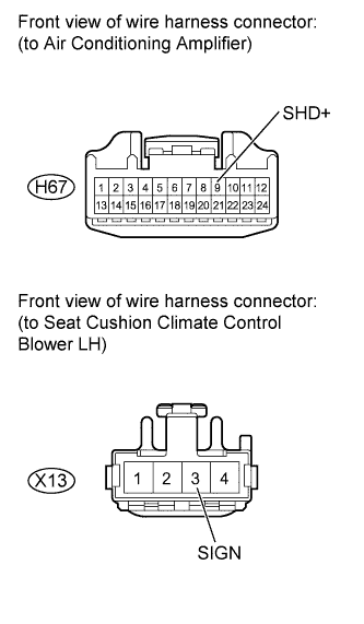 |
Disconnect the H67 amplifier connector.
Disconnect the X13 blower connector.
Measure the resistance according to the value(s) in the table below.
| Tester Connection | Condition | Specified Condition |
| H67-9 (SHD+) - X13-3 (SIGN) | Always | Below 1 Ω |
| H67-9 (SHD+) - Body ground | Always | 10 kΩ or higher |
|
| ||||
| OK | |
|
| 8.CHECK HARNESS AND CONNECTOR (SEAT HEATER SWITCH LH) |
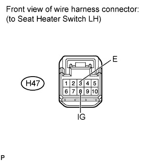 |
Disconnect the H47 switch connector.
Measure the voltage and resistance according to the value(s) in the table below.
| Tester Connection | Condition | Specified Condition |
| H47-3 (E) - Body ground | Always | Below 1 Ω |
| Tester Connection | Switch Condition | Specified Condition |
| H47-8 (IG) - Body ground | Ignition switch ON | 11 to 14 V |
|
| ||||
| OK | |
|
| 9.INSPECT SEAT HEATER SWITCH LH |
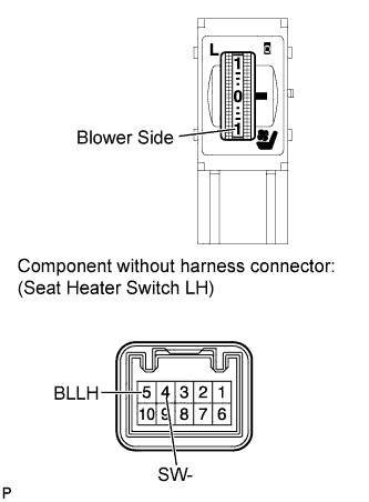 |
Remove the seat heater switch (Click here).
Measure the resistance according to the value(s) in the table below.
| Tester Connection | Condition | Specified Condition |
| 5 (BLLH) - 4 (SW-) | Seat Heater switch OFF | 1.54 to 2.86 kΩ |
| Seat heater switch blower side volume 3 | Below 0.1 kΩ |
|
| ||||
| OK | |
|
| 10.CHECK HARNESS AND CONNECTOR (SEAT HEATER SWITCH LH - AIR CONDITIONING AMPLIFIER) |
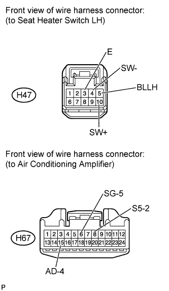 |
Disconnect the H67 amplifier connector.
Disconnect the H47 switch connector.
Measure the resistance according to the value(s) in the table below.
| Tester Connection | Condition | Specified Condition |
| H47-3 (E) - Body ground | Always | Below 1 Ω |
| H47-4 (SW-) - H67-6 (SG-5) | Always | Below 1 Ω |
| H47-4 (SW-) - Body ground | Always | 10 kΩ or higher |
| H47-5 (BLLH) - H67-15 (AD-4) | Always | Below 1 Ω |
| H47-5 (BLLH) - Body ground | Always | 10 kΩ or higher |
| H47-10 (SW+) - H67-8 (S5-2) | Always | Below 1 Ω |
| H47-10 (SW+) - Body ground | Always | 10 kΩ or higher |
|
| ||||
| OK | ||
| ||
| ||
| 11.CHECK HARNESS AND CONNECTOR (SEAT CLIMATE CONTROL BLOWER RH - BATTERY AND BODY GROUND) |
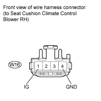 |
Disconnect the W16 blower connector.
Measure the voltage and resistance according to the value(s) in the table below.
| Tester Connection | Switch Condition | Specified Condition |
| W16-1 (IG) - Body ground | Ignition switch ON | 11 to 14 V |
| Tester Connection | Condition | Specified Condition |
| W16-4 (GND) - Body ground | Always | Below 1 Ω |
Reconnect the W16 blower connector.
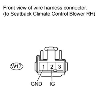 |
Disconnect the W17 blower connector.
Measure the voltage and resistance according to the value(s) in the table below.
| Tester Connection | Condition | Specified Condition |
| W17-1 (GND) - Body ground | Always | Below 1 Ω |
| Tester Connection | Switch Condition | Specified Condition |
| W17-2 (IG) - Body ground | Ignition switch ON | 11 to 14 V |
|
| ||||
| OK | |
|
| 12.INSPECT SEAT CLIMATE CONTROL BLOWER RH |
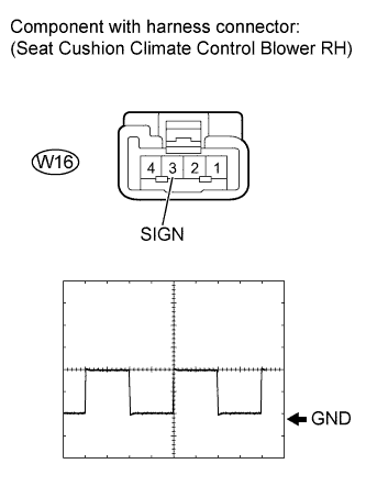 |
Check the input signal waveform.
Connect an oscilloscope to terminal W16-3 (SIGN) and body ground with the climate control blower connector still connected.
Check the signal waveform according to the condition(s) in the table below.
| Terminal No. (Symbol) | Tool setting | Condition |
| W16-3 (SIGN) - Body ground | 2 V/DIV., 500 μsec/DIV. | Ignition switch ON Seat heater switch blower side volume 3 |
| Result | Proceed to |
| NG | A |
| OK (Seat cushion blower side) | B |
| OK (Seatback blower side) | C |
|
| ||||
|
| ||||
| A | |
|
| 13.CHECK HARNESS AND CONNECTOR (AIR CONDITIONING AMPLIFIER - SEAT CLIMATE CONTROL BLOWER RH) |
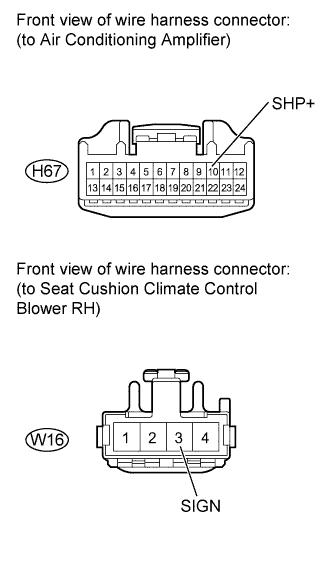 |
Disconnect the H67 amplifier connector.
Disconnect the W16 blower connector.
Measure the resistance according to the value(s) in the table below.
| Tester Connection | Condition | Specified Condition |
| H67-10 (SHP+) - W16-3 (SIGN) | Always | Below 1 Ω |
| H67-10 (SHP+) - Body ground | Always | 10 kΩ or higher |
|
| ||||
| OK | |
|
| 14.CHECK HARNESS AND CONNECTOR (SEAT HEATER SWITCH RH) |
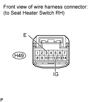 |
Disconnect the H49 switch connector.
Measure the voltage and resistance according to the value(s) in the table below.
| Tester Connection | Condition | Specified Condition |
| H49-3 (E) - Body ground | Always | Below 1 Ω |
| Tester Connection | Switch Condition | Specified Condition |
| H49-12 (IG) - Body ground | Ignition switch ON | 11 to 14 V |
|
| ||||
| OK | |
|
| 15.INSPECT SEAT HEATER SWITCH RH |
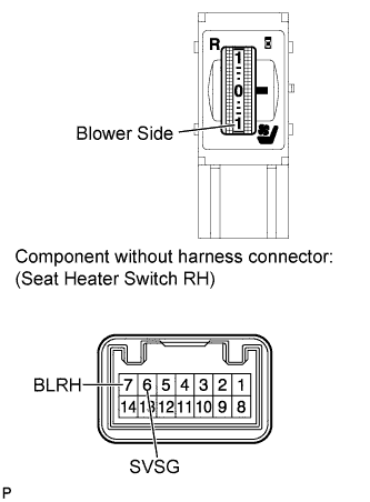 |
Remove the seat heater switch (Click here).
Measure the resistance according to the value(s) in the table below.
| Tester Connection | Condition | Specified Condition |
| 7 (BLRH) - 6 (SVSG) | Seat Heater switch OFF | 1.54 to 2.86 kΩ |
| Seat heater switch blower side volume 3 | Below 0.1 kΩ |
|
| ||||
| OK | |
|
| 16.CHECK HARNESS AND CONNECTOR (SEAT HEATER SWITCH RH - AIR CONDITIONING AMPLIFIER) |
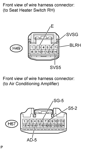 |
Disconnect the H67 amplifier connector.
Disconnect the H49 switch connector.
Measure the resistance according to the value(s) in the table below.
| Tester Connection | Condition | Specified Condition |
| H49-3 (E) - Body ground | Always | Below 1 Ω |
| H49-6 (SVSG) - H67-6 (SG- 5) | Always | Below 1 Ω |
| H49-6 (SVSG) - Body ground | Always | 10 kΩ or higher |
| H49-7 (BLRH) - H67-16 (AD-5) | Always | Below 1 Ω |
| H49-7 (BLRH) - Body ground | Always | 10 kΩ or higher |
| H49-14 (SVS5) - H67-8 (S5-2) | Always | Below 1 Ω |
| H49-14 (SVS5) - Body ground | Always | 10 kΩ or higher |
|
| ||||
| OK | ||
| ||
| ||

