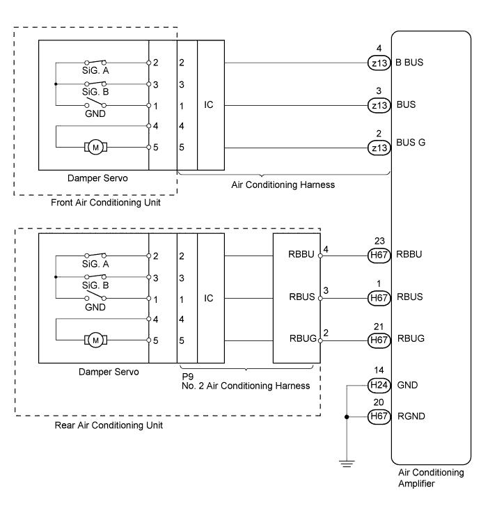
DTC B1497/97 BUS IC Communication Malfunction |
| DTC Code | DTC Detection Condition | Trouble Area |
| B1497/97 | Communication line error or open |
|
| 1.CHECK AIR CONDITIONING SYSTEM CONTROL |
Check that the air conditioning system control.
| Result | Proceed to |
| OK | A |
| NG (Front and rear air conditioning system control is malfunction) | B |
| NG (Front air conditioning system control is malfunction) | C |
| NG (Rear air conditioning system control is malfunction) | D |
|
| ||||
|
| ||||
|
| ||||
| A | |
 |
| 2.CHECK FOR DTC |
Clear the DTC (Click here).
Check for DTC (Click here).
|
| ||||
| OK | ||
 | ||
| ||
| 3.CHECK HARNESS AND CONNECTOR (AIR CONDITIONING AMPLIFIER - BODY GROUND) |
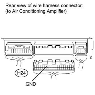 |
Disconnect the H24 air conditioning amplifier connector.
Measure the resistance according to the value(s) in the table below.
| Tester Connection | Condition | Specified Condition |
| H24-14 (GND) - Body ground | Always | Below 1 Ω |
|
| ||||
| OK | |
|
| 4.INSPECT AIR CONDITIONING AMPLIFIER |
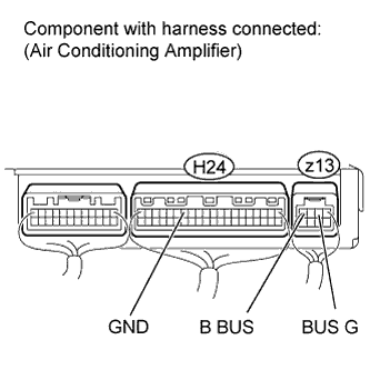 |
Reconnect the H24 air conditioning amplifier connector.
Measure the resistance and voltage according to the value(s) in the table below.
| Tester Connection | Condition | Specified Condition |
| H24-14 (GND) - z13-2 (BUS G) | Always | Below 1 Ω |
| Tester Connection | Switch Condition | Specified Condition |
| z13-4 (B BUS) - z13-2 (BUS G) | Ignition switch ON | 11 to 14 V |
| Ignition switch off | Below 1 V |
|
| ||||
| OK | |
|
| 5.REPAIR OR REPLACE AIR CONDITIONING HARNESS |
Repair or replace the air conditioning harness (Click here).
| NEXT | |
|
| 6.CHECK FOR DTC |
Clear the DTC (Click here).
Check for DTC (Click here).
|
| ||||
| OK | ||
| ||
| ||
| 7.CHECK HARNESS AND CONNECTOR (AIR CONDITIONING AMPLIFIER - BODY GROUND) |
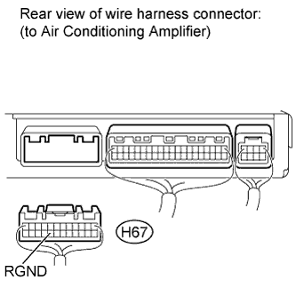 |
Disconnect the H67 air conditioning amplifier connector.
Measure the resistance according to the value(s) in the table below.
| Tester Connection | Condition | Specified Condition |
| H67-20 (RGND) - Body ground | Always | Below 1 Ω |
|
| ||||
| OK | |
|
| 8.CHECK HARNESS AND CONNECTOR (AIR CONDITIONING AMPLIFIER - NO. 2 AIR CONDITIONING HARNESS) |
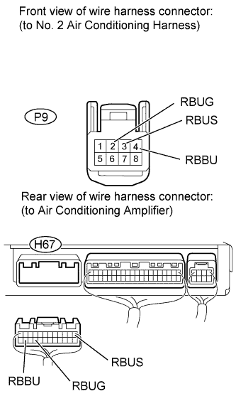 |
Disconnect the P9 rear air conditioning harness connector.
Measure the resistance according to the value(s) in the table below.
| Tester Connection | Condition | Specified Condition |
| P9-2 (RBUG) - H67-21 (RBUG) | Always | Below 1 Ω |
| P9-3 (RBUS) - H67-1 (RBUS) | Always | Below 1 Ω |
| P9-4 (RBBU) - H67-23 (RBBU) | Always | Below 1 Ω |
| H67-21 (RBUG) - Body ground | Always | 10 KΩ or higher |
| H67-1 (RBUS) - Body ground | Always | 10 KΩ or higher |
| H67-23 (RBBU) - Body ground | Always | 10 KΩ or higher |
Reconnect the air conditioning amplifier connector.
Reconnect the rear air conditioning harness connector.
|
| ||||
| OK | |
|
| 9.CHECK AIR CONDITIONING AMPLIFIER |
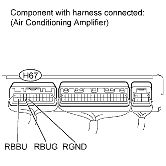 |
Measure the resistance and voltage according to the value(s) in the table below.
| Tester Connection | Condition | Specified Condition |
| H67-20 (RGND) - H67-21 (RBUG) | Always | Below 1 Ω |
| Tester Connection | Switch Condition | Specified Condition |
| H67-23 (RBBU) - H67-21 (RBUG) | Ignition switch ON | 11 to 14 V |
| Ignition switch off | Below 1 V |
|
| ||||
| OK | |
|
| 10.REPAIR OR REPLACE NO.2 AIR CONDITIONING HARNESS |
Repair or replace the No. 2 air conditioning harness (Click here).
| NEXT | |
|
| 11.CHECK FOR DTC |
Clear the DTC (Click here).
Check for DTC (Click here).
|
| ||||
| OK | ||
| ||
| ||

