 |
Remove the oil filler cap.
CAMSHAFT > REMOVAL |
| 1. DISCHARGE FUEL SYSTEM PRESSURE |
| 2. DISCONNECT CABLE FROM NEGATIVE BATTERY TERMINAL |
| 3. DRAIN ENGINE OIL |
|
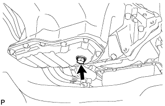
Remove the oil filler cap.
Remove the oil drain plug and gasket, and drain the engine oil into a container.
Install a new gasket and the oil pan drain plug.
| 4. REMOVE TIMING BELT |
Remove the timing belt (Click here).
| 5. DISCONNECT VACUUM HOSE ASSEMBLY |
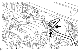 |
Remove the bolt and disconnect the vacuum hose assembly.
| 6. REMOVE FUEL PIPE CLAMP |
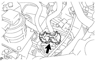 |
Remove the fuel pipe clamp.
| 7. DISCONNECT NO. 2 FUEL PIPE SUB-ASSEMBLY |
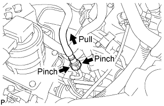 |
Pinch the retainer as illustrated, and then pull the fuel tube connector out of the pipe.
| 8. DISCONNECT NO. 1 FUEL PIPE SUB-ASSEMBLY |
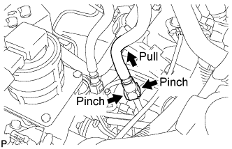 |
Pinch the retainer as illustrated, and then pull the fuel tube connector out of the pipe.
| 9. REMOVE FUEL PRESSURE PULSATION DAMPER ASSEMBLY |
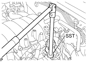 |
Using SST, remove the pulsation damper and 2 gaskets.
| 10. REMOVE AIR SWITCHING VALVE ASSEMBLY |
Remove the air switching valve assembly (Click here)
| 11. SEPARATE ENGINE WIRE |
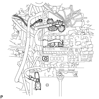 |
Remove the nut and disconnect the wire from the positive (+) battery terminal.
Disconnect the positive (+) battery terminal.
Remove the bolt and disconnect the ground wire.
Disconnect the 4 air injection control driver connectors.
Remove the nut and disconnect the wire from the engine room junction block.
Disconnect the 3 connectors from the engine room junction block.
| 12. REMOVE IGNITION COIL ASSEMBLY |
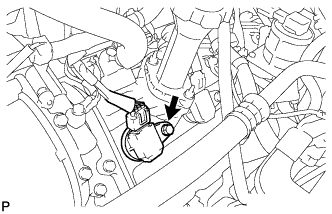 |
Disconnect the 8 ignition coil assembly connectors.
Remove the 8 bolts and pull out the 8 ignition coil assemblies.
| 13. REMOVE SPARK PLUG |
Using a 16 mm plug wrench, remove the 8 spark plugs.
| 14. DISCONNECT NO. 5 WATER BY-PASS HOSE |
Disconnect the No. 5 water by-pass hose from the No. 3 water by-pass pipe.
| 15. DISCONNECT INLET HEATER WATER HOSE D |
Disconnect the inlet heater water hose D from the No. 3 water by-pass pipe.
| 16. REMOVE NO. 1 WATER BY-PASS PIPE |
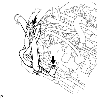 |
Remove the 2 bolts and water by-pass pipe.
| 17. REMOVE VENTILATION HOSE |
Remove the ventilation hose.
| 18. REMOVE CYLINDER HEAD COVER SUB-ASSEMBLY LH |
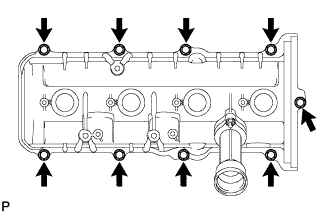 |
Remove the 9 bolts, cylinder head cover and gasket.
| 19. REMOVE CAMSHAFT POSITION SENSOR ASSEMBLY |
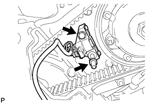 |
Remove the bolt, stud bolt and camshaft position sensor.
| 20. REMOVE CAMSHAFT TIMING PULLEY SUB-ASSEMBLY LH |
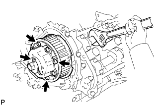 |
Hold the hexagonal portion of the camshaft with a wrench and remove the 4 bolts indicated by the arrows in the illustration and timing pulley.
| 21. REMOVE REAR TIMING BELT PLATE LH |
Remove the 3 bolts, No. 1 timing belt plate and No. 2 timing belt plate.
| 22. REMOVE CAMSHAFT SUB-ASSEMBLY (for Bank 1) |
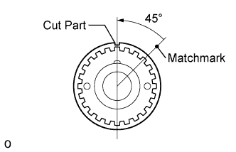 |
Check that the timing mark of the crankshaft timing pulley is in the position shown in the illustration, and that the piston is below the TDC of compression.
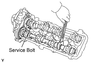 |
Bring the service bolt hole of the sub-gear upward by turning the hexagonal portion of the exhaust camshaft with a wrench.
Secure the sub-gear to the main gear with a service bolt.
| Thread Diameter | Thread Pitch | Bolt Length |
| 6.0 mm | 1.0 mm | 16 to 20 mm (0.630 to 0.787 in.) |
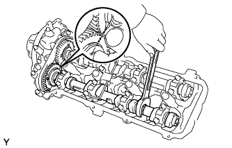 |
Using a wrench, turn the camshaft so that the timing marks (2 dot marks each) on the camshaft drive and driven main gears are aligned, as shown in the illustration.
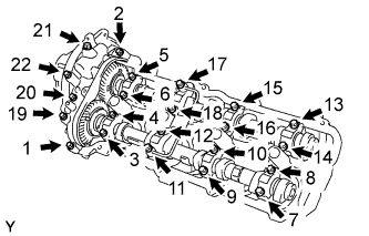 |
Uniformly loosen and remove the 22 bearing cap bolts in several steps, in the order shown in the illustration.
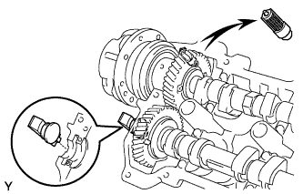 |
Remove the cap bolts, 4 seal washers, oil feed pipe, 9 bearing caps, camshaft housing plug, oil control valve filter and camshafts.
| 23. REMOVE CYLINDER HEAD COVER SUB-ASSEMBLY |
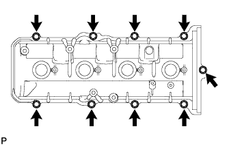 |
Remove the 9 bolts, cylinder head cover and gasket.
| 24. REMOVE CAMSHAFT TIMING PULLEY |
Hold the hexagonal portion of the camshaft with a wrench and remove the 4 bolts indicated by the arrows in the illustration and timing pulley.
| 25. REMOVE REAR TIMING BELT PLATE RH |
Remove the 4 bolts, No. 2 timing belt plate and No. 1 timing belt plate.
| 26. REMOVE CAMSHAFT (for Bank 2) |
|
Check that the timing mark of the crankshaft timing pulley is in the position shown in the illustration, and that the piston is below the TDC of compression.
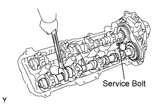 |
Bring the service bolt hole of the sub-gear upward by turning the hexagonal portion of the exhaust camshaft with a wrench.
Secure the sub-gear to the main gear with a service bolt.
| Thread Diameter | Thread Pitch | Bolt Length |
| 6.0 mm | 1.0 mm | 16 to 20 mm (0.630 to 0.787 in.) |
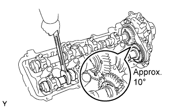 |
Using a wrench, turn the camshaft so that the timing marks (1 dot marks each) on the camshaft drive and driven main gears are aligned, as shown in the illustration.
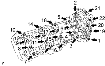 |
Uniformly loosen and remove the 22 bearing cap bolts in several steps, in the order shown in the illustration.
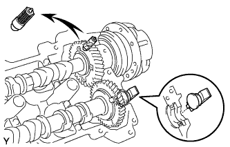 |
Remove the cap bolts, 4 seal washers, oil feed pipe, 9 bearing caps, camshaft housing plug, oil control valve filter and camshafts.
| 27. REMOVE CAMSHAFT TIMING TUBE ASSEMBLY |
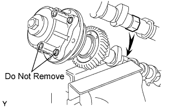 |
Mount the hexagonal portion of the camshaft in a vise.
Remove the screw plug and seal washer.
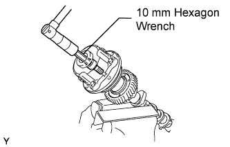 |
Using a 10 mm hexagon wrench, remove the bolt.
Pull out the timing tube and drive gear assembly from the camshaft.
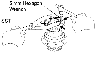 |
Using SST and a 5 mm hexagon wrench, remove the 4 bolts, drive gear and oil seal.
| 28. REMOVE NO. 3 CAMSHAFT SUB GEAR |
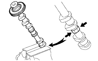 |
Mount the hexagonal portion of the camshaft in a vise.
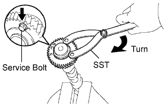 |
Using SST, turn the sub-gear clockwise, and remove the service bolt.
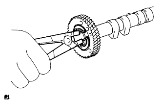 |
Using snap ring pliers, remove the snap ring.
Remove the wave washer, sub-gear and gear spring.