 |
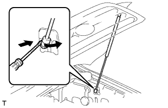
Using a screwdriver, release the 2 clips and remove the hood support assembly.
- HINT:
- Tape the screwdriver tip before use.
- CAUTION:
- Remove the hood support assembly while supporting the hood by hand.
ENGINE ASSEMBLY > REMOVAL |
| 1. DISCHARGE FUEL SYSTEM PRESSURE |
Connect the Techstream to the DLC3.
Turn the ignition switch to ON.
Turn the Techstream main switch on.
Enter the following menus: Powertrain / Engine and ECT / Active Test / Control the Fuel Pump / Speed.
Check the fuel pump operation.
Check for pressure in the fuel inlet tube from the fuel line. Check that the sound of fuel flowing in the fuel tank can be heard.
If there is no sound, check the integration relay, fuel pump, ECM and wiring connector.
Check for fuel leaks.
Check that there are no fuel leaks after performing maintenance anywhere on the system.
If there are fuel leaks, repair or replace parts as necessary.
| 2. DISCONNECT CABLE FROM NEGATIVE BATTERY TERMINAL |
| 3. DRAIN ENGINE OIL |
Remove the oil filler cap.
Remove the oil pan drain plug and gasket, and drain the engine oil into a container.
Install a new gasket and the oil pan drain plug.
| 4. REMOVE HOOD SUB-ASSEMBLY |
|
Using a screwdriver, release the 2 clips and remove the hood support assembly.
Remove the 4 bolts and hood.
| 5. REMOVE WINDSHIELD WIPER MOTOR ASSEMBLY |
Remove the windshield wiper motor (Click here).
| 6. REMOVE COWL TOP OUTER PANEL SUB-ASSEMBLY |
Disconnect the 2 washer hoses.
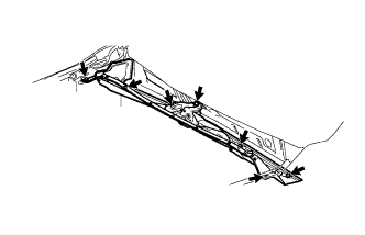 |
Remove the 7 bolts and outer panel.
| 7. REMOVE RADIATOR ASSEMBLY |
Remove the radiator assembly (Click here).
| 8. REMOVE AUTOMATIC TRANSMISSION ASSEMBLY |
Remove the transmission assembly (Click here).
| 9. REMOVE AIR CLEANER ASSEMBLY |
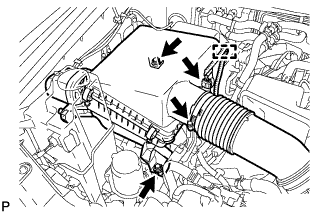 |
Loosen the hose clamp and disconnect the air cleaner from the air cleaner hose.
Loosen the 2 bolts and remove the air cleaner with the grommet.
| 10. REMOVE AIR CLEANER HOSE ASSEMBLY |
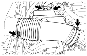 |
Disconnect the vacuum hose and ventilation hose.
Loosen the 2 clamps.
Remove the air cleaner hose.
| 11. DISCONNECT INLET HEATER WATER HOSE C |
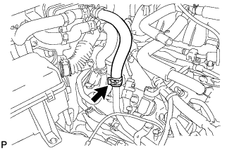 |
Disconnect the inlet heater water hose from the No. 1 water by-pass pipe.
| 12. DISCONNECT OUTLET HEATER WATER HOSE C |
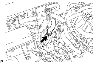 |
Disconnect the outlet heater water hose from the water by-pass pipe.
| 13. DISCONNECT VACUUM HOSE ASSEMBLY |
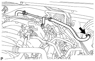 |
Disconnect the vacuum hose from the brake booster.
| 14. REMOVE FUEL VAPOR FEED HOSE ASSEMBLY |
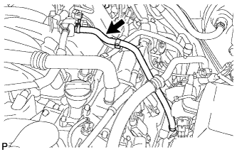 |
Remove the fuel vapor feed hose.
| 15. DISCONNECT FUEL MAIN AND RETURN HOSE |
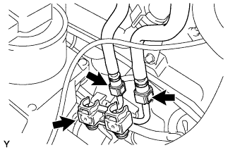 |
Remove the fuel pipe clamp.
Disconnect the fuel main and return hoses (Click here).
| 16. SEPARATE ECM |
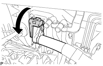 |
Disconnect the clamp and ECM connector.
| 17. SEPARATE ENGINE WIRE |
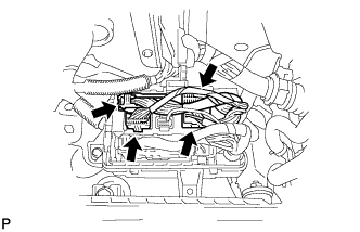 |
Disconnect the 4 connectors from the connector holder block.
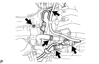 |
Remove the nut and connector bracket and disconnect the 2 air pump connectors.
Remove the bolt and disconnect the ground wire.
Disconnect the 2 air injection system hoses.
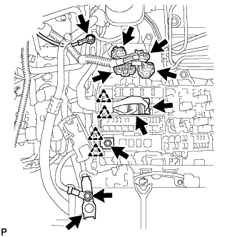 |
Remove the nut and disconnect the wire from the positive (+) battery cable.
Disconnect the cable from the positive (+) battery terminal.
Remove the bolt and disconnect the ground wire.
Disconnect the 4 air injection control driver connectors.
Remove the nut and disconnect the wire and 2 clips from the engine room junction block.
Disconnect the 2 connectors and 2 clips from the engine room junction block.
| 18. DISCONNECT NO. 3 AIR INJECTION SYSTEM HOSE |
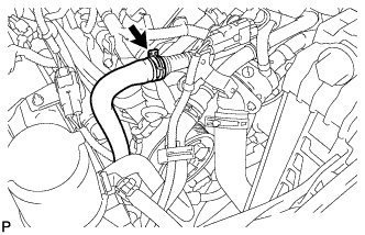 |
Disconnect the No. 3 air injection hose.
| 19. DISCONNECT NO. 2 AIR INJECTION SYSTEM HOSE |
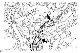 |
Disconnect the connector and separate the wire harness clamp.
Disconnect the No. 2 air injection hose.
| 20. SEPARATE COOLER COMPRESSOR ASSEMBLY |
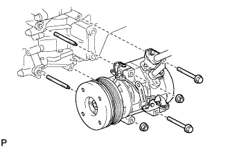 |
Remove the 2 bolts, 2 nuts and 2 stud bolts, and disconnect the cooler compressor.
| 21. REMOVE GENERATOR ASSEMBLY |
Remove the generator assembly (Click here).
| 22. REMOVE EXHAUST MANIFOLD |
Remove the exhaust manifold (Click here).
| 23. REMOVE DRIVE PLATE AND RING GEAR SUB-ASSEMBLY |
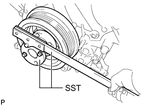 |
Using SST, hold the crankshaft.
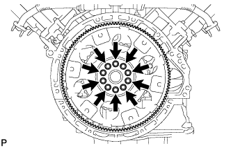 |
Remove the 10 bolts, rear drive plate spacer, drive plate and crankshaft angle sensor rotor.
| 24. REMOVE NO. 1 WATER BY-PASS PIPE |
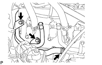 |
Remove the 2 bolts and disconnect the hose, and then remove the water by-pass pipe.
| 25. REMOVE OIL COOLER TUBE |
Remove the bolt and oil cooler tube from the oil pan.
| 26. REMOVE ENGINE ASSEMBLY |
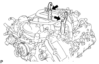 |
Install the 2 engine hangers with the 2 bolts as shown in the illustration.
| Item | Part No. |
| Engine hanger | 12281-38030, 12281-38060 |
| Bolt | 90119-14120, 90119-A0166 |
Attach an engine sling device and hang the engine with a chain block.
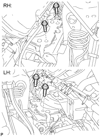 |
Remove the 4 engine mounting insulator bolts.
Lift the engine out from the vehicle slowly and carefully.
| 27. INSTALL ENGINE ON ENGINE STAND |
Install the engine onto an engine stand with the bolts.
Remove the 2 bolts and 2 engine hangers.