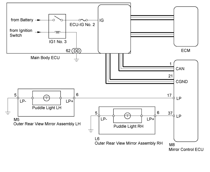
LIGHTING SYSTEM > Door Mirror Foot Light Circuit |
| 1.PERFORM ACTIVE TEST USING TECHSTREAM (FOOT LIGHT) |
Connect the Techstream to the DLC3.
Turn the ignition switch to ON.
Turn the Techstream on.
Enter the following menus: Body Electrical / Mirror ECU / Active Test / Foot Light.
Check that the Puddle light turns on/off.
| Tester Display | Test Part | Control Range | Diagnostic Note |
| Foot Light | Puddle light | ON or OFF | - |
|
| ||||
| OK | |
 |
| 2.CHECK CAN COMMUNICATION SYSTEM |
Check for CAN communication system DTCs output.
|
| ||||
| OK | |
|
| 3.CHECK VEHICLE CONDITION |
Identify the control system where the problem occurs.
| Result | Proceed to |
| All of the following apply | A |
| When changing the shift position | B |
| When operating the ignition switch | C |
| When opening or closing a door | D |
| When operating a door lock | E |
|
| ||||
|
| ||||
|
| ||||
|
| ||||
| A | ||
 | ||
| ||
| 4.READ VALUE USING TECHSTREAM (SHIFT SW STATUS (P RANGE)) |
Connect the Techstream to the DLC3.
Turn the ignition switch to ON.
Turn the Techstream on.
Enter the following menus:
for 2UZ-FE engine model: Powertrain / ECT / Data List / Shift SW Status (P Range)
for 3UR-FE, 3UR-FBE engine model: Powertrain / Engine and ECT / Data List / Shift SW Status (P Range)
According to the display on the Techstream, read the Data List.
| Tester Display | Measurement Item/Range | Normal Condition | Diagnostic Note |
| Shift SW Status (P Range) | PNP switch status/ ON or OFF | Shift lever is:
| When shift lever position displayed on Techstream differs from actual position, adjustment of PNP switch or shift cable may be incorrect |
| Result | Proceed to |
| OK | A |
| NG (for 2UZ-FE two wheel drive model) | B |
| NG (for 2UZ-FE four wheel drive model) | C |
| NG (for 3UR-FE, 3UR-FBE two wheel drive model) | D |
| NG (for 3UR-FE, 3UR-FBE four wheel drive model) | E |
|
| ||||
|
| ||||
|
| ||||
|
| ||||
| A | ||
| ||
| ||
| 5.READ VALUE USING TECHSTREAM (IG SW) |
Connect the Techstream to the DLC3.
Turn the ignition switch to ON.
Turn the Techstream on.
Enter the following menus: Body Electrical / Main Body / Data List / IG SW.
According to the display on the Techstream, read the Data List.
| Tester Display | Measurement Item/Range | Normal Condition | Diagnostic Note |
| IG SW | Ignition switch status/ ON or OFF | Ignition switch is:
| - |
|
| ||||
| OK | ||
| ||
| ||
| 6.INSPECT FUSE (ECU-IG NO. 2) |
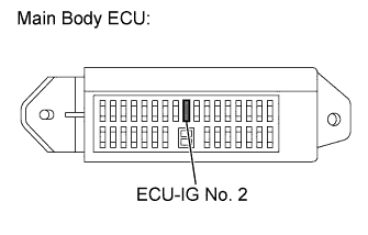 |
Remove the ECU-IG No. 2 fuse from the main Body ECU.
Measure the resistance according to the value(s) in the table below.
| Tester Connection | Condition | Specified Condition |
| ECU-IG No. 2 fuse | Always | Below 1 Ω |
Reinstall the ECU-IG No. 2 fuse.
|
| ||||
| OK | ||
| ||
| ||
| 7.READ VALUE USING TECHSTREAM (COURTESY SWITCH) |
Connect the Techstream to the DLC3.
Turn the ignition switch to ON.
Turn the Techstream on.
Enter the following menus: Body Electrical / Main Body / Data List.
According to the display on the Techstream, read the Data List.
| Tester Display | Measurement Item/Range | Normal Condition | Diagnostic Note |
| D Door Courtesy SW | Front door courtesy light switch LH signal / ON or OFF | ON: Front door courtesy light switch LH ON OFF: Front door courtesy light switch LH OFF | - |
| P Door Courtesy SW | Front door courtesy light switch RH signal / ON or OFF | ON: Front door courtesy light switch RH ON OFF: Front door courtesy light switch RH OFF | - |
|
| ||||
| OK | ||
| ||
| ||
| 8.READ VALUE USING TECHSTREAM (DOOR LOCK POSITION SWITCH) |
Connect the Techstream to the DLC3.
Turn the ignition switch to ON.
Turn the Techstream on.
Enter the following menus: Body Electrical / Main Body / Data List / D-Door Lock Pos SW.
According to the display on the Techstream, read the Data List.
| Tester Display | Measurement Item/Range | Normal Condition | Diagnostic Note |
| D-Door Lock Pos SW | Front door lock switch signal / ON or OFF | ON: Front door lock switch ON OFF: Front door lock switch OFF | - |
|
| ||||
| OK | ||
| ||
| ||
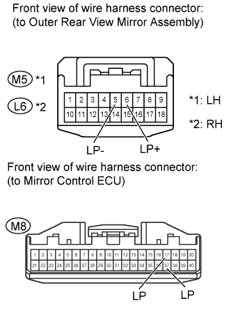
| 9.CHECK HARNESS AND CONNECTOR (OUTER REAR VIEW MIRROR - MIRROR ECU, BODY GROUND) |
 |
for LH:
Disconnect the M5 outer rear view mirror assembly LH connector.
Disconnect the M8 mirror control ECU connector.
Measure the resistance according to the value(s) in the table below.
| Tester Connection | Condition | Specified Condition |
| M5-6 (LP+) - M8-17 (LP) | Always | Below 1 Ω |
| M5-5 (LP-) - Body Ground | Always | Below 1 Ω |
| M5-6 (LP+) - Body Ground | Always | 10 kΩ or higher |
Reconnect the mirror control ECU connector.
Reconnect the outer rear view mirror assembly LH connector.
for RH:
Disconnect the L6 outer rear view mirror assembly RH connector.
Disconnect the M8 mirror control ECU connector.
Measure the resistance according to the value(s) in the table below.
| Tester Connection | Condition | Specified Condition |
| L6-6 (LP+) - M8-37 (LP) | Always | Below 1 Ω |
| L6-5 (LP-) - Body Ground | Always | Below 1 Ω |
| L6-6 (LP+) - Body Ground | Always | 10 kΩ or higher |
Reconnect the mirror control ECU connector.
Reconnect the outer rear view mirror assembly RH connector.
|
| ||||
| OK | |
|
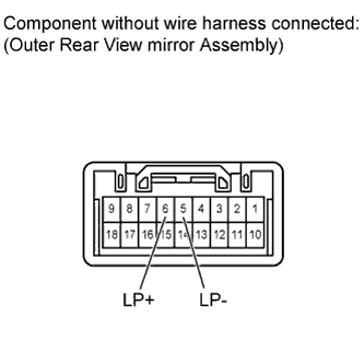
| 10.INSPECT OUTER REAR VIEW MIRROR ASSEMBLY |
 |
Remove the outer rear view mirror assembly (Click here).
Apply battery voltage to the terminals and check that the puddle light turn on.
| Measurement Connection | Specified Condition |
| Positive battery (+) → 6 (LP+) Negative battery (-) → 5 (LP-) | Puddle light turn on. |
Reinstall the outer rear view mirror assembly.
|
| ||||
| OK | ||
| ||
| ||
| 11.INSPECT PUDDLE LIGHT |
Temporarily replace the puddle light bulb with a new or normally functioning one (Click here).
Check that the puddle light turn on.
|
| ||||
| OK | ||
| ||
| ||

