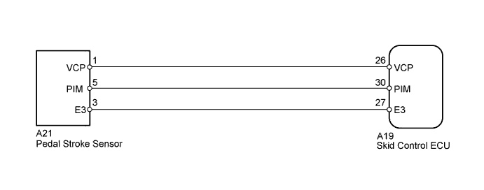
DTC C1247/47 Stroke Sensor Malfunction |
| DTC Code | DTC Detection Condition | Trouble Area |
| C1247/47 | When either condition below is met:
|
|
| 1.READ VALUE USING TECHSTREAM (STROKE SENSOR) |
Connect the Techstream to the DLC3.
Turn the ignition switch to ON.
Run the engine until the engine reaches 3000 rpm, and return it back to idle.
Select the Data List mode on the Techstream.
| Tester Display | Measurement Item/Range | Normal Condition | Diagnostic Note |
| Stroke Sensor | Pedal stroke sensor / min.: 0.00 V, max.: 5.00 V | Approximately 1.90 V without the brake pedal depressed. | - |
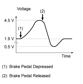 |
Check that the brake pedal acceleration value of the pedal stroke sensor displayed on the Techstream changes by alternately depressing and releasing the brake pedal.
| NEXT | |
 |
| 2.CHECK HARNESS AND CONNECTOR (PEDAL STROKE SENSOR - SKID CONTROL ECU) |
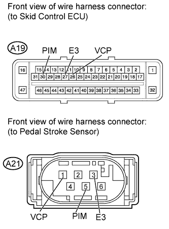 |
Confirm that the skid control ECU connector and pedal stroke sensor connector are properly connected.
Disconnect the A19 ECU connector.
Disconnect the A21 sensor connector.
Inspect both the connector case and the terminal for deformation and corrosion.
Measure the resistance according to the value(s) in the table below.
| Tester Connection | Condition | Specified Condition |
| A19-30 (PIM) - A21-5 (PIM) | Always | Below 1 Ω |
| A19-30 (PIM) - Body ground | Always | 10 kΩ or higher |
| A19-27 (E3) - A21-3 (E3) | Always | Below 1 Ω |
| A19-27 (E3) - Body ground | Always | 10 kΩ or higher |
| A19-26 (VCP) - A21-1 (VCP) | Always | Below 1 Ω |
| A19-26 (VCP) - Body ground | Always | 10 kΩ or higher |
|
| ||||
| OK | |
|
| 3.INSPECT BRAKE BOOSTER ASSEMBLY (PEDAL STROKE SENSOR) |
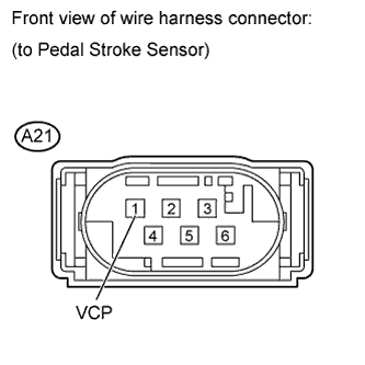 |
Disconnect the A21 sensor connector.
Turn the ignition switch to ON.
Measure the voltage according to the value(s) in the table below.
| Tester Connection | Switch Condition | Specified Condition |
| A21-1 (VCP) - Body ground | Ignition switch ON | 5.0 V |
|
| ||||
| OK | ||
 | ||
| ||
