 |
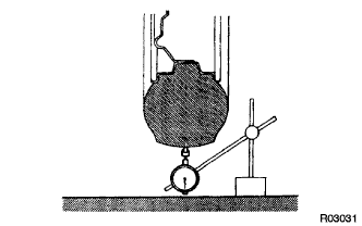
Using a dial indicator, check the tire runout.
- Tire runout:
- 3.0 mm (0.118 in.) or less
REAR WHEEL ALIGNMENT > ADJUSTMENT |
| 1. INSPECT TIRE |
Check the tires for wear and proper inflation pressure.
| Tire Size | Front kPa (kgf/cm2, psi) | Rear kPa (kgf/cm2, psi) |
| P275/65R18 | 230 (2.3, 33) | 230 (2.3, 33) |
| P275/55R20 | 210 (2.1, 30) | 230 (2.3, 33) |
|
Using a dial indicator, check the tire runout.
| 2. MEASURE VEHICLE HEIGHT |
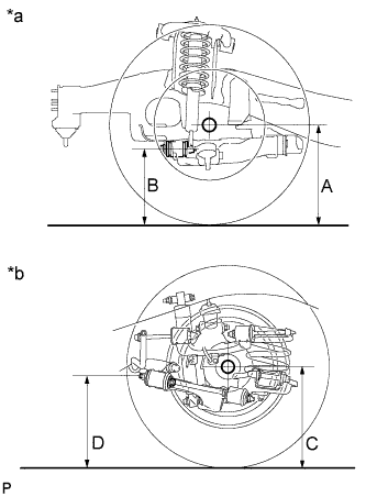 |
Press down on the vehicle several times to stabilize the suspension, and then measure the vehicle height.
| *a | Front Side |
| *b | Rear Side |
| Vehicle Model | Tire Size | Front A - B | Rear C - D |
| UPK60L-GKTSKA | P275/65R18 8JJ | 106.2 mm (4.18 in.) | 29.3 mm (1.15 in.) |
| P275/55R20 8JJ | 106.2 mm (4.18 in.) | 29.3 mm (1.15 in.) | |
| UPK60L-GKTLKA | P275/65R18 8JJ | 106.1 mm (4.18 in.) | 30.0 mm (1.18 in.) |
| P275/55R20 8JJ | 106.1 mm (4.18 in.) | 30.0 mm (1.18 in.) | |
| UPK65L-GKTSKA | P275/65R18 8JJ | 101.7 mm (4.00 in.) | 24.8 mm (0.98 in.) |
| P275/55R20 8JJ | 101.7 mm (4.00 in.) | 24.8 mm (0.98 in.) | |
| UPK65L-GKTLKA | P275/65R18 8JJ | 101.4 mm (3.99 in.) | 25.1 mm (0.99 in.) |
| P275/55R20 8JJ | 101.4 mm (3.99 in.) | 25.1 mm (0.99 in.) | |
| USK60L-GKTSKA | P275/65R18 8JJ | 108.1 mm (4.26 in.) | 30.3 mm (1.19 in.) |
| P275/55R20 8JJ | 108.1 mm (4.26 in.) | 30.3 mm (1.19 in.) | |
| USK60L-GKTLKA | P275/65R18 8JJ | 107.6 mm (4.24 in.) | 30.6 mm (1.20 in.) |
| P275/55R20 8JJ | 107.6 mm (4.24 in.) | 30.6 mm (1.20 in.) | |
| USK60L-GKTZKA | P275/55R20 8JJ | 106.6 mm (4.20 in.) | 39.1 mm (1.54 in.) |
| USK65L-GKTSKA | P275/65R18 8JJ | 101.9 mm (4.01 in.) | 25.2 mm (0.99 in.) |
| P275/55R20 8JJ | 101.9 mm (4.01 in.) | 25.2 mm (0.99 in.) | |
| USK65L-GKTLKA | P275/65R18 8JJ | 101.7 mm (4.00 in.) | 25.3 mm (1.00 in.) |
| P275/55R20 8JJ | 101.7 mm (4.00 in.) | 25.3 mm (1.00 in.) | |
| USK65L-GKTZKA | P275/55R20 8JJ | 100.3 mm (3.95 in.) | 34.0 mm (1.34 in.) |
| USK65L-GKTSGA | P275/65R18 8JJ | 101.9 mm (4.01 in.) | 25.2 mm (0.99 in.) |
| P275/55R20 8JJ | 101.9 mm (4.01 in.) | 25.2 mm (0.99 in.) | |
| USK65L-GKTLGA | P275/65R18 8JJ | 101.7 mm (4.00 in.) | 25.3 mm (1.00 in.) |
| P275/55R20 8JJ | 101.7 mm (4.00 in.) | 25.3 mm (1.00 in.) | |
| USK65L-GKTZGA | P275/55R20 8JJ | 100.3 mm (3.95 in.) | 34.0 mm (1.34 in.) |
| 3. INSPECT CAMBER |
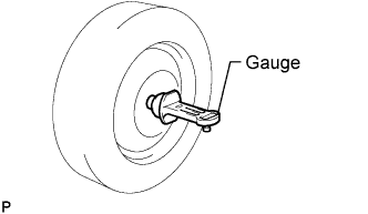 |
Install a camber-caster-kingpin gauge or put the wheels on a wheel alignment tester.
Inspect the camber.
| Drive Type | Rear Suspension Type | Camber Inclination |
| 2WD | Coil | -1°25' +/-45' (-1.42°+/-0.75°) |
| Air | -1°41' +/-45' (-1.68°+/-0.75°) | |
| 4WD | Coil | -1°17' +/-45' (-1.28°+/-0.75°) |
| Air | -1°33' +/-45' (-1.55°+/-0.75°) |
| 4. ADJUST CAMBER |
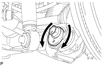 |
Loosen the camber adjust cam nut.
Rotate the camber adjust cam on the vehicle side of No. 2 lower arm to adjust camber.
| Drive Type | Rear Suspension Type | Camber Inclination |
| 2WD | Coil | -1°25' +/-45' (-1.42°+/-0.75°) |
| Air | -1°41' +/-45' (-1.68°+/-0.75°) | |
| 4WD | Coil | -1°17' +/-45' (-1.28°+/-0.75°) |
| Air | -1°33' +/-45' (-1.55°+/-0.75°) |
Tighten the nut.
| 5. INSPECT TOE-IN |
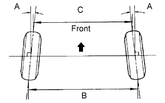 |
| Drive Type | Rear Suspension Type | Specified Condition |
| 2WD | Coil | A: -0°02' +/-4' (-0.03°+/-0.07°) B - C: -1.0 +/-2 mm (-0.0394 +/-0.0787 in.) |
| Air | A: -0°01' +/-4' (-0.02°+/-0.07°) B - C: -0.3 +/-2 mm (-0.0118 +/-0.0787 in.) | |
| 4WD | Coil | A: -0°03' +/-4' (-0.05°+/-0.07°) B - C: -1.4 +/-2 mm (-0.0551 +/-0.0787 in.) |
| Air | A: -0°02' +/-4' (-0.03°+/-0.07°) B - C: -0.7 +/-2 mm (-0.0276 +/-0.0787 in.) |
| 6. ADJUST TOE-IN |
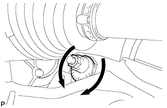 |
Loosen the toe adjust cam bolt.
Rotate the toe adjust plate on the vehicle side of lower arm No. 2 to adjust toe-in.
| Drive Type | Rear Suspension Type | Specified Condition |
| 2WD | Coil | A: -0°02' +/-4' (-0.03°+/-0.07°) B - C: -1.0 +/-2 mm (-0.0394 +/-0.0787 in.) |
| Air | A: -0°01' +/-4' (-0.02°+/-0.07°) B - C: -0.3 +/-2 mm (-0.0118 +/-0.0787 in.) | |
| 4WD | Coil | A: -0°03' +/-4' (-0.05°+/-0.07°) B - C: -1.4 +/-2 mm (-0.0551 +/-0.0787 in.) |
| Air | A: -0°02' +/-4' (-0.03°+/-0.07°) B - C: -0.7 +/-2 mm (-0.0276 +/-0.0787 in.) |
Tighten the bolt.
| 7. DISCONNECT CABLE FROM NEGATIVE BATTERY TERMINAL |
| 8. CONNECT CABLE TO NEGATIVE BATTERY TERMINAL |
| 9. PERFORM YAW RATE SENSOR ZERO POINT CALIBRATION |
| 10. CHECK STEERING ANGLE SENSOR ZERO POINT CALIBRATION |