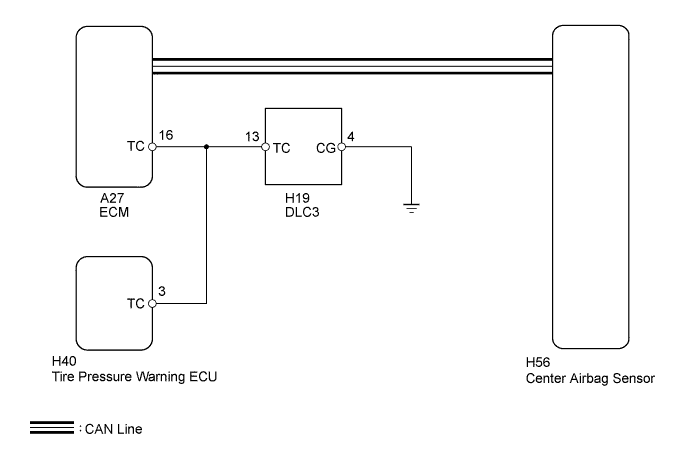
AIRBAG SYSTEM > Diagnosis Circuit |
| 1.CHECK CAN COMMUNICATION SYSTEM |
Check if a CAN communication system DTC is output (Click here).
| Result | Proceed to |
| DTC is not output | A |
| DTC is output | B |
|
| ||||
| A | |
 |
| 2.CHECK HARNESS AND CONNECTOR (DLC3 - ECM) |
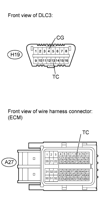 |
Turn the ignition switch off.
Disconnect the A27 ECM connector.
Measure the resistance according to the value(s) in the table below.
| Tester Connection | Condition | Specified Condition |
| H19-13 (TC) - A27-16 (TC) | Always | Below 1 Ω |
|
| ||||
| OK | |
|
| 3.CHECK HARNESS AND CONNECTOR (DLC3 - BODY GROUND) |
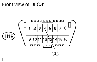 |
Measure the resistance according to the value(s) in the table below.
| Tester Connection | Condition | Specified Condition |
| H19-4 (CG) - Body ground | Always | Below 1 Ω |
|
| ||||
| OK | |
|
| 4.CHECK HARNESS AND CONNECTOR (TC OF ECM - BODY GROUND) |
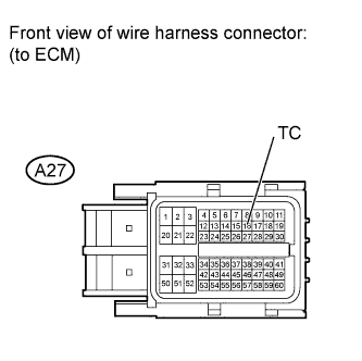 |
Measure the resistance according to the value(s) in the table below.
| Tester Connection | Condition | Specified Condition |
| A27-16 (TC) - Body ground | Always | 1 MΩ or higher |
| Result | Proceed to |
| OK (for 1UR-FE) | A |
| OK (for 3UR-FE) | B |
| OK (for 3UR-FBE) | C |
| NG | D |
|
| ||||
|
| ||||
|
| ||||
| A | ||
 | ||
| ||
