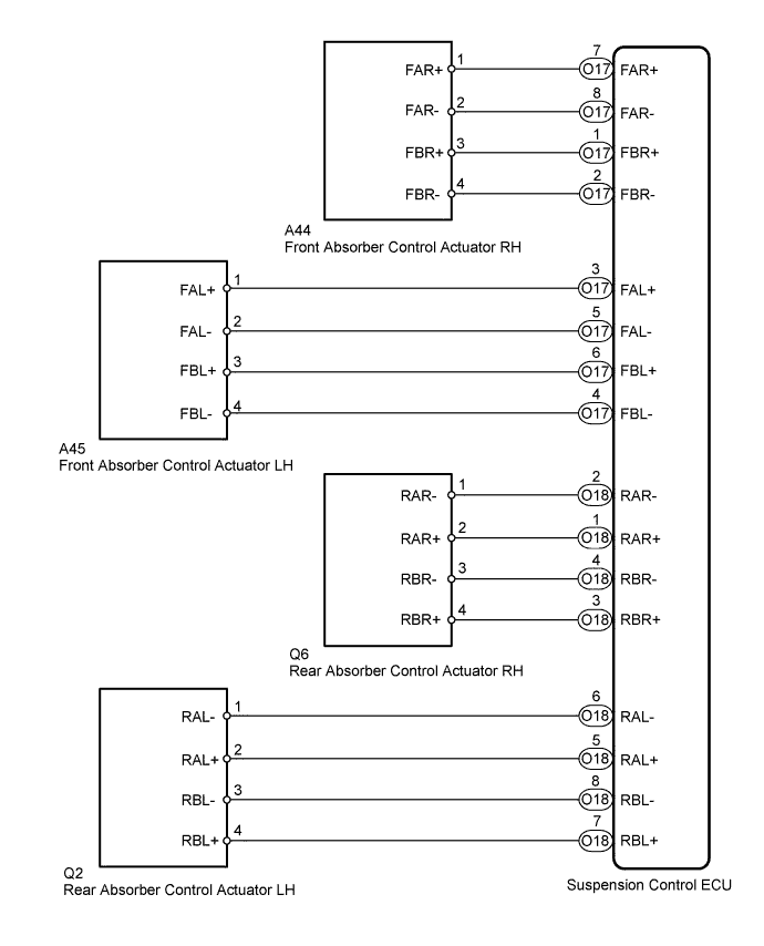
DTC C1731 Front Damping Force Control Actuator RH Circuit Malfunction |
DTC C1732 Front Damping Force Control Actuator LH Circuit Malfunction |
DTC C1733 Rear Damping Force Control Actuator RH Circuit Malfunction |
DTC C1734 Rear Damping Force Control Actuator LH Circuit Malfunction |
| DTC Code | Detection Condition | Trouble Area |
| C1731 | When either of the following is detected:
|
|
| C1732 | When either of the following is detected:
|
|
| C1733 | When either of the following is detected:
|
|
| C1734 | When either of the following is detected:
|
|
| 1.PERFORM ACTIVE TEST USING TECHSTREAM (REAR GATE SOLENOID) |
Turn the ignition switch off.
Connect the Techstream to the DLC3.
Turn the ignition switch to ON, and turn the Techstream main switch on.
Enter the following menus: Chassis / Air suspension / Active Test.
| Tester Display | Test Part | Control Range | Diagnostic Note |
| Damper Step FR | Damper step (Front RH) / min.: 0 step max.: 255 steps | min.: 1 step max.: 16 steps | - |
| Damper Step FL | Damper step (Front LH) / min.: 0 step max.: 255 steps | min.: 1 step max.: 16 steps | - |
| Damper Step RR | Damper step (Rear RH) / min.: 0 step max.: 255 steps | min.: 1 step max.: 16 steps | - |
| Damper Step RL | Damper step (Rear LH) / min.: 0 step max.: 255 steps | min.: 1 step max.: 16 steps | - |
|
| ||||
| OK | ||
 | ||
| ||
| 2.INSPECT ABSORBER CONTROL ACTUATOR |
Turn the ignition switch off.
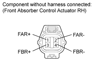 |
Check the front absorber control actuator RH: (C1731).
Disconnect the A44 actuator connector.
Measure the resistance according to the value(s) in the table below.
| Tester Connection | Sensor Condition | Specified Condition |
| 1 (FAR+) - 2 (FAR-) | Always | 6.4 to 7.2 Ω |
| 3 (FBR+) - 4 (FBR-) | Always | 6.4 to 7.2 Ω |
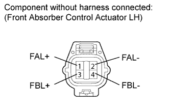 |
Check the front absorber control actuator LH: (C1732).
Disconnect the A45 actuator connector.
Measure the resistance according to the value(s) in the table below.
| Tester Connection | Sensor Condition | Specified Condition |
| 1 (FAL+) - 2 (FAL-) | Always | 6.4 to 7.2 Ω |
| 3 (FBL+) - 4 (FBL-) | Always | 6.4 to 7.2 Ω |
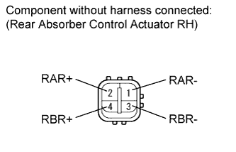 |
Check the rear absorber control actuator RH: (C1733).
Disconnect the Q6 actuator connector.
Measure the resistance according to the value(s) in the table below.
| Tester Connection | Sensor Condition | Specified Condition |
| 1 (RAR-) - 2 (RAR+) | Always | 6.4 to 7.2 Ω |
| 3 (RBR-) - 4 (RBR+) | Always | 6.4 to 7.2 Ω |
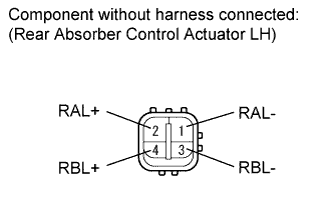 |
Check the rear absorber control actuator LH: (C1734).
Disconnect the Q2 actuator connector.
Measure the resistance according to the value(s) in the table below.
| Tester Connection | Sensor Condition | Specified Condition |
| 1 (RAL-) - 2 (RAL+) | Always | 6.4 to 7.2 Ω |
| 3 (RBL-) - 4 (RBL+) | Always | 6.4 to 7.2 Ω |
| Result | Proceed to |
| OK | A |
| NG (Front absorber control actuator RH) | B |
| NG (Front absorber control actuator LH) | C |
| NG (Rear absorber control actuator RH) | D |
| NG (Rear absorber control actuator LH) | E |
|
| ||||
|
| ||||
|
| ||||
|
| ||||
| A | |
 |
| 3.CHECK HARNESS AND CONNECTOR (ABSORBER CONTROL ACTUATOR - ECU AND BODY GROUND) |
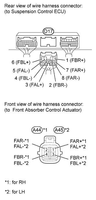 |
Check the front side absorber control actuator.
Connect the A44 or A45 front absorber control actuator connector.
Disconnect the O17 ECU connector.
Measure the resistance according to the value(s) in the table below.
| Tester Connection | Condition | Specified Condition |
| A44-1 (FAR+) - O17-7 (FAR+) | Always | Below 1 Ω |
| A44-2 (FAR-) - O17-8 (FAR-) | Always | Below 1 Ω |
| A44-3 (FBR+) - O17-1 (FBR+) | Always | Below 1 Ω |
| A44-4 (FBR-) - O17-2 (FBR-) | Always | Below 1 Ω |
| A44-1 (FAR+) or O17-7 (FAR+) - Body ground | Always | 10 kΩ or higher |
| A44-2 (FAR-) or O17-8 (FAR-) - Body ground | Always | 10 kΩ or higher |
| A44-3 (FBR+) or O17-1 (FBR+) - Body ground | Always | 10 kΩ or higher |
| A44-4 (FBR-) or O17-2 (FBR-) - Body ground | Always | 10 kΩ or higher |
| Tester Connection | Condition | Specified Condition |
| A45-1 (FAL+) - O17-3 (FAL+) | Always | Below 1 Ω |
| A45-2 (FAL-) - O17-5 (FAL-) | Always | Below 1 Ω |
| A45-3 (FBL+) - O17-6 (FBL+) | Always | Below 1 Ω |
| A45-4 (FBL-) - O17-4 (FBL-) | Always | Below 1 Ω |
| A45-1 (FAL+) or O17-3 (FAL+) - Body ground | Always | 10 kΩ or higher |
| A45-2 (FAL-) or O17-5 (FAL-) - Body ground | Always | 10 kΩ or higher |
| A45-3 (FBL+) or O17-6 (FBL+) - Body ground | Always | 10 kΩ or higher |
| A45-4 (FBL-) or O17-4 (FBL-) - Body ground | Always | 10 kΩ or higher |
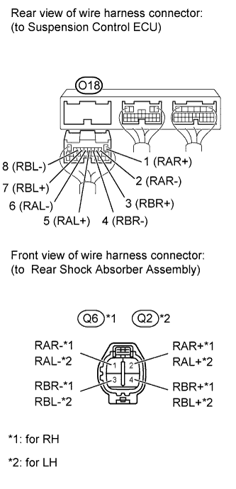 |
Check the rear side absorber control actuator.
Connect the Q2 or Q6 rear absorber control actuator connector.
Disconnect the O18 ECU connector.
Measure the resistance according to the value(s) in the table below.
| Tester Connection | Condition | Specified Condition |
| Q6-1 (RAR-) - O18-2 (RAR-) | Always | Below 1 Ω |
| Q6-2 (RAR+) - O18-1 (RAR+) | Always | Below 1 Ω |
| Q6-3 (RBR-) - O18-4 (RBR-) | Always | Below 1 Ω |
| Q6-4 (RBR+) - O18-3 (RBR+) | Always | Below 1 Ω |
| Q6-1 (RAR-) or O18-2 (RAR-) - Body ground | Always | 10 kΩ or higher |
| Q6-2 (RAR+) or O18-1 (RAR+) - Body ground | Always | 10 kΩ or higher |
| Q6-3 (RBR-) or O18-4 (RBR-) - Body ground | Always | 10 kΩ or higher |
| Q6-4 (RBR+) or O18-3 (RBR+) - Body ground | Always | 10 kΩ or higher |
| Tester Connection | Condition | Specified Condition |
| Q2-1 (RAL-) - O18-6 (RAL-) | Always | Below 1 Ω |
| Q2-2 (RAL+) - O18-5 (RAL+) | Always | Below 1 Ω |
| Q2-3 (RBL-) - O18-8 (RBL-) | Always | Below 1 Ω |
| Q2-4 (RBL+) - O18-7 (RBL+) | Always | Below 1 Ω |
| Q2-1 (RAL-) or O18-6 (RAL-) - Body ground | Always | 10 kΩ or higher |
| Q2-2 (RAL+) or O18-5 (RAL+) - Body ground | Always | 10 kΩ or higher |
| Q2-3 (RBL-) or O18-8 (RBL-) - Body ground | Always | 10 kΩ or higher |
| Q2-4 (RBL+) or O18-7 (RBL+) - Body ground | Always | 10 kΩ or higher |
|
| ||||
| OK | ||
| ||
| ||

