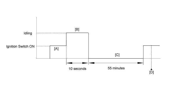
DTC P106A Evaporative Emission System Pressure Sensor - Manifold Absolute Pressure Correlation |
DTC P106B Evaporative Emission System Pressure Sensor - Secondary Air Injection Pressure Sensor Correlation |
| DTC No. | DTC Detection Condition | Trouble Area |
| P106A | The pressure detected by the canister pressure sensor (Vapor Pressure Pump*) and the pressure detected by the manifold absolute pressure sensor (MAP*) differ by 7 kPa (54 mmHg) or more (2 trip detection logic) |
|
| P106B | The pressure detected by the canister pressure sensor (Vapor Pressure Pump*) and the pressure detected by the pressure sensor of either air switching valve (for Bank 1 or Bank 2) (Air Pump Pressure (Absolute)* or Air Pump2 Pressure (Absolute)*) differ by 6.98 kPa (52 mmHg) or more (2 trip detection logic) |
|
| Related DTCs | P106A: Evaporative emission system pressure sensor - manifold absolute pressure correlation P106B: Evaporative emission system pressure sensor - secondary air injection system pressure sensor correlation |
| Required Sensors/Components (Main) |
|
| Required Sensors/Components (Related) | - |
| Frequency of Operation | Once per drive cycle |
| Duration | Less than 65 seconds |
| MIL Operation | 2 driving cycles |
| Sequence of Operation | None |
| Monitor runs whenever following DTCs not present | P0107, P0108 (Manifold absolute pressure) P0401 (EGR system) P0452, P0453 (EVAP system, Evaporative emission system pressure sensor) |
| Time elapsed after engine stop | 50 minutes |
| Time after ECM started by soak-timer | 60 seconds or more |
| Battery voltage | 10.5 V or more |
| Intake air temperature | -10°C (14°F) or more |
| Engine coolant temperature | -10°C (14°F) or more |
| Monitor runs whenever following DTCs not present | P0452, P0453 (EVAP system) P2431, P2432, P2433, P2436, P2437, P2438 (Secondary air injection system pressure sensor) P2440, P2441, P2442, P2443, P2444, P2445, P2446, P2447 (Secondary air injection system) |
| Time elapsed after engine stop | 50 minutes |
| Time after ECM started by soak-timer | 60 seconds or more |
| Battery voltage | 10.5 V or more |
| Intake air temperature | -10°C (14°F) or more |
| Engine coolant temperature | -10°C (14°F) or more |
| Difference between EVAP pressure and manifold absolute pressure | More than 7.22 kPa (54 mmHg, 2.13 in.Hg) |
| Difference between EVAP pressure (Vapor Pressure Pump*) and secondary air pressure sensor (bank 1) (Air Pump Pressure (Absolute)*) | More than 6.98 kPa (52 mmHg, 2.06 in.Hg) |
| Difference between EVAP pressure (Vapor Pressure Pump*) and secondary air pressure sensor (bank 2) (Air Pump2 Pressure (Absolute)*) | More than 6.98 kPa (52 mmHg, 2.06 in.Hg) |
| Techstream Display | Description |
| NORMAL |
|
| ABNORMAL |
|
| INCOMPLETE |
|
| N/A |
|
| 1.CHECK ANY OTHER DTCS OUTPUT (IN ADDITION TO P106A, P106B) |
Connect the Techstream to the DLC3.
Turn the ignition switch to ON.
Turn the Techstream on.
Enter the following menus: Powertrain / Engine and ECT / Trouble Codes.
Read the DTCs.
| Result | Proceed to |
| DTC P106A is output | A |
| DTC P106B is output | B |
| DTC P106A and P106B are output | C |
| DTC P106A, P106B and other are output | D |
|
| ||||
|
| ||||
|
| ||||
| A | |
 |
| 2.REPLACE MANIFOLD ABSOLUTE PRESSURE SENSOR |
Replace the manifold absolute pressure sensor (Click here).
|
| ||||
| 3.READ VALUE USING TECHSTREAM (AIR PUMP PRESSURE (ABSOLUTE) AND AIR PUMP2 PRESSURE (ABSOLUTE)) |
Connect the Techstream to the DLC3.
Turn the ignition switch to ON.
Turn the Techstream on.
Enter the following menus: Powertrain / Engine and ECT / Data List / Air Pump Pressure (Absolute), Air Pump2 Pressure (Absolute) and Vapor Pressure Pump.
Read the value.
| Result | Proceed to |
| Difference between Air Pump Pressure (Absolute) and Vapor Pressure Pump is more than 3.5 kPa (26 mmHg, 1.03 in.Hg) | A |
| Difference between Air Pump2 Pressure (Absolute) and Vapor Pressure Pump is more than 3.5 kPa (26 mmHg, 1.03 in.Hg) | B |
|
| ||||
| A | |
|
| 4.REPLACE AIR SWITCHING VALVE (FOR BANK 1) |
Replace the air switching valve for bank 1 (Click here).
|
| ||||
| 5.REPLACE AIR SWITCHING VALVE (FOR BANK 2) |
Replace the air switching valve for bank 2 (Click here).
|
| ||||
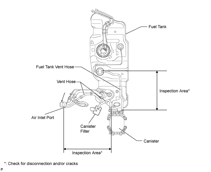
| 6.REPLACE CANISTER |
Replace the canister (Click here).
| NEXT | |
|
| 7.CONFIRM WHETHER MALFUNCTION HAS BEEN SUCCESSFULLY REPAIRED |
Connect the Techstream to the DLC3.
Turn the ignition switch to ON and turn the Techstream on.
Clear the DTCs (Click here).
Enter the following menus: Powertrain / Engine and ECT / Data List.
Compare the Data List items Air Pump Pressure (Absolute) and Vapor Pressure Pump, Air Pump2 Pressure (Absolute) and Vapor Pressure Pump, and Vapor Pressure Pump and MAP.
Confirm that the difference between Vapor Pressure Pump and MAP, and between Vapor Pressure Pump, Air Pump Pressure (Absolute) and Air Pump2 Pressure (Absolute) is 3.5 kPa (26 mmHg. 1.03 in.Hg) or less.
| NEXT | ||
 | ||
| ||

