Home › Engine / Hybrid System › 3UR-FBE ENGINE MECHANICAL › CAMSHAFT › 2015.08–2016.10
RM27L0U _51 Engine / Hybrid System _049295 3UR-FBE ENGINE MECHANICAL _0235550 CAMSHAFT A

3UR-FBE ENGINE MECHANICAL  CAMSHAFT  INSTALLATION  


PROCEDURE

Hide 1.INSTALL CAMSHAFTS (for Bank 1)

a.

Apply a light coat of engine oil to the camshaft journals, camshaft housings and bearing caps.
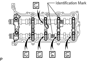

b.
A316365E01
1.991,0.021 3.161,0.205 1.170,0.185 10 Identification Mark 1.96,0.105 1.702,0.105 1.702,0.105 1.889,1.297 false 1.702,0.105 2.212,0.777 false

Install the No. 3 and No. 4 camshafts to the camshaft housing.

HINT:

Check the identification mark stamped on the camshaft.

Item Mark
for Intake Side NO. 3
for Exhaust Side NO. 4


c.

Confirm the marks and numbers on the camshaft bearing caps and place them in their proper positions and directions.
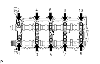

d.
U151457E02
0.615,1.75 0.719,1.896 0.104,0.146 10 true 1 0.594,0.26 0.698,0.406 0.104,0.146 10 true 2 1.229,1.781 1.333,1.927 0.104,0.146 10 true 3 1.219,0.25 1.323,0.396 0.104,0.146 10 false 4 1.708,1.781 1.813,1.927 0.104,0.146 10 false 5 1.688,0.25 1.792,0.396 0.104,0.146 10 false 6 2.198,1.771 2.302,1.917 0.104,0.146 10 true 7 2.188,0.271 2.292,0.417 0.104,0.146 10 false 8 2.75,1.75 2.865,1.896 0.115,0.146 10 false 9 2.698,0.271 2.885,0.427 0.188,0.156 10 false 10

Temporarily install the 10 bolts in the order shown in the illustration.


Hide 11104A 2.INSTALL CAMSHAFT HOUSING SUB-ASSEMBLY LH
U151598E02
1.854,0.604 2.656,0.813 2.656,0.813 2.656,0.948 false 0.958,0.896 2.563,1.917 2.563,1.917 2.563,2.063 true 1.979,0.146 3.135,0.354 1.156,0.208 10 false Valve Rocker Arm 2.094,0.979 3.135,1.219 1.042,0.24 10 false Valve Stem Cap 1.885,1.958 3.156,2.146 1.271,0.188 10 false Valve Lash Adjuster 0.25,2.729 1,2.948 0.75,0.219 10 false CORRECT 0.229,1.135 1.188,1.375 0.958,0.24 10 false INCORRECT

a.

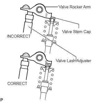
Make sure that the valve rocker arms are installed as shown in the illustration.

b.
A380006E01
0.781,1.688 2.594,1.906 1.813,0.219 10 false Seal diameter: 3.5 to 4.0 mm

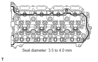
Apply seal packing in a continuous line as shown in the illustration.

Seal packing:

Toyota Genuine Seal Packing Black, Three Bond 1207B or equivalent


Standard seal diameter:

3.5 to 4.0 mm (0.138 to 0.157 in.)


NOTICE:
·

Remove any oil from the contact surface.

·

Install the camshaft housing within 3 minutes and tighten the bolts within 15 minutes after applying seal packing.


c.
A163732E06
0.917,2.583 1.813,2.938 1.813,2.938 2.51,2.573 false 1.51,0.552 1.615,0.708 0.104,0.156 10 true 1 1.042,0.552 1.146,0.708 0.104,0.156 10 true 2 2.156,0.552 2.26,0.708 0.104,0.156 10 true 3 0.406,0.563 0.51,0.719 0.104,0.156 10 true 4 2.802,0.552 2.948,0.719 0.146,0.167 10 true 5 1.604,0 1.708,0.156 0.104,0.156 10 false 6 1.521,1.885 1.625,2.042 0.104,0.156 10 false 7 1.042,0 1.146,0.156 0.104,0.156 10 false 8 1.031,1.885 1.135,2.042 0.104,0.156 10 false 9 2.135,0 2.323,0.156 0.188,0.156 10 false 10 2.083,1.885 2.271,2.042 0.188,0.156 10 false 11 0.354,0 0.542,0.156 0.188,0.156 10 false 12 0.365,1.885 0.552,2.042 0.188,0.156 10 false 13 3.208,0.531 3.396,0.688 0.188,0.156 10 false 14 2.646,1.844 2.833,2 0.188,0.156 10 false 15 0.052,1.406 0.24,1.563 0.188,0.156 10 false 16 2.979,1.438 3.167,1.594 0.188,0.156 10 false 17 1.302,2.094 1.49,2.271 0.188,0.177 10 false IN 2.875,2.125 3.146,2.26 0.271,0.135 10 false EX 1.448,2.927 2.125,3.094 0.677,0.167 10 false Knock Pin 2.5,2.073 2.781,2.25 0.281,0.177 10 false 3° 0.698,2.083 1.01,2.292 0.313,0.208 10 false 45° 3.208,0.021 3.396,0.177 0.188,0.156 10 false 18 2.885,0.021 3.021,0.188 0.135,0.167 10 false A

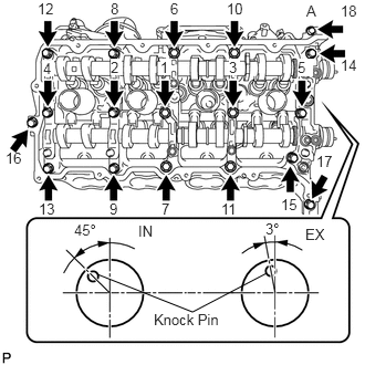
Install the camshaft housing, and install the 18 bolts in the order shown in the illustration.

Torque:
for bolt A : 10 N*m (102 kgf*cm, 7 ft.*lbf)
except bolt A : 30 N*m (306 kgf*cm, 22 ft.*lbf)

NOTICE:
·

Do not start the engine for at least 2 hours after the installation.

·

Make sure that the knock pin of the camshaft is positioned as shown in the illustration before installing the camshaft housing.


d.
A163592E07
2.885,0.208 3,0.396 0.115,0.188 10 true 1 2.875,1.729 2.99,1.917 0.115,0.188 10 true 2 2.188,0.198 2.302,0.385 0.115,0.188 10 true 3 2.156,1.729 2.271,1.917 0.115,0.188 10 false 4 1.625,0.198 1.74,0.385 0.115,0.188 10 true 5 1.604,1.729 1.719,1.917 0.115,0.188 10 false 6 1.073,0.208 1.188,0.396 0.115,0.188 10 true 7 1.021,1.729 1.135,1.917 0.115,0.188 10 false 8 0.438,0.219 0.552,0.406 0.115,0.188 10 true 9 0.385,1.729 0.563,1.917 0.177,0.188 10 false 10

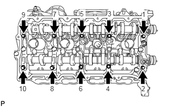
Tighten the 10 bolts in the order shown in the illustration.

Torque:
16 N*m (163 kgf*cm, 12 ft.*lbf)

NOTICE:

Thoroughly wipe clean any seal packing.


Hide 3.INSTALL CAMSHAFTS (for Bank 2)

a.

Apply a light coat of engine oil to the camshaft journals, camshaft housings and bearing caps.
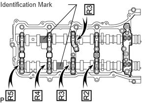

b.
A316364E01
0.006,0.007 1.179,0.187 1.173,0.180 10 Identification Mark 1.446,0.097 1.627,0.097 1.627,0.097 1.275,1.408 false 1.625,0.097 0.919,0.834 false

Install the No. 1 and No. 2 camshafts to the camshaft housing.

HINT:

Check the identification mark stamped on the camshaft.

Item Mark
for Intake Side NO. 1
for Exhaust Side NO. 2


c.

Confirm the marks and numbers on the camshaft bearing caps and place them in their proper positions and directions.
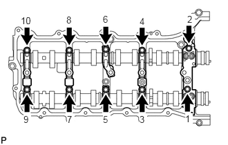

d.
A160687E06
2.792,1.708 2.906,1.875 0.115,0.167 10 true 1 2.823,0.208 2.938,0.375 0.115,0.167 10 true 2 2.104,1.719 2.219,1.885 0.115,0.167 10 true 3 2.104,0.24 2.219,0.406 0.115,0.167 10 false 4 1.552,1.719 1.667,1.885 0.115,0.167 10 true 5 1.552,0.208 1.667,0.375 0.115,0.167 10 false 6 1.01,1.719 1.125,1.885 0.115,0.167 10 true 7 1,0.219 1.115,0.385 0.115,0.167 10 false 8 0.354,1.719 0.469,1.885 0.115,0.167 10 true 9 0.313,0.229 0.5,0.396 0.188,0.167 10 false 10

Temporarily install the 10 bolts in the order shown in the illustration.


Hide 11103C 4.INSTALL CAMSHAFT HOUSING SUB-ASSEMBLY RH

U151598E02
1.854,0.604 2.656,0.813 2.656,0.813 2.656,0.948 false 0.958,0.896 2.563,1.917 2.563,1.917 2.563,2.063 true 1.979,0.146 3.135,0.354 1.156,0.208 10 false Valve Rocker Arm 2.094,0.979 3.135,1.219 1.042,0.24 10 false Valve Stem Cap 1.885,1.958 3.156,2.146 1.271,0.188 10 false Valve Lash Adjuster 0.25,2.729 1,2.948 0.75,0.219 10 false CORRECT 0.229,1.135 1.188,1.375 0.958,0.24 10 false INCORRECT

a.

Make sure that the valve rocker arms are installed as shown in the illustration.
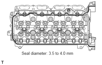

b.
A380007E01
0.729,1.708 2.625,1.927 1.896,0.219 10 false Seal diameter: 3.5 to 4.0 mm

Apply seal packing in a continuous line as shown in the illustration.

Seal packing:

Toyota Genuine Seal Packing Black, Three Bond 1207B or equivalent


Standard seal diameter:

3.5 to 4.0 mm (0.138 to 0.157 in.)


NOTICE:
·

Remove any oil from the contact surface.

·

Install the camshaft housing within 3 minutes and tighten the bolts within 15 minutes after applying seal packing.
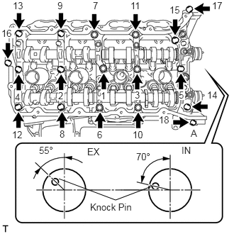


c.
A163556E06
0.865,2.625 1.698,2.938 1.698,2.938 2.25,2.729 false 1.479,1.323 1.573,1.479 0.094,0.156 10 true 1 0.854,1.323 0.948,1.479 0.094,0.156 10 true 2 1.979,1.313 2.073,1.469 0.094,0.156 10 true 3 0.219,1.344 0.313,1.5 0.094,0.156 10 true 4 2.625,1.313 2.719,1.469 0.094,0.156 10 true 5 1.427,1.896 1.521,2.052 0.094,0.156 10 false 6 1.365,0 1.458,0.156 0.094,0.156 10 false 7 0.875,1.885 0.969,2.042 0.094,0.156 10 false 8 0.844,0 0.938,0.156 0.094,0.156 10 false 9 1.948,1.896 2.135,2.052 0.188,0.156 10 false 10 1.917,0 2.104,0.156 0.188,0.156 10 false 11 0.177,1.896 0.365,2.052 0.188,0.156 10 false 12 0.188,0 0.375,0.156 0.188,0.156 10 false 13 3.042,1.313 3.229,1.469 0.188,0.156 10 false 14 2.49,0.063 2.677,0.219 0.188,0.156 10 false 15 3.115,0 3.302,0.156 0.188,0.156 10 false 17 2.333,1.677 2.521,1.833 0.188,0.156 10 true 18 0.021,0.406 0.208,0.563 0.188,0.156 10 true 16 1.323,2.958 2.021,3.125 0.698,0.167 10 false Knock Pin 0.573,2.125 0.948,2.323 0.375,0.198 10 false 55° 2,2.219 2.375,2.417 0.375,0.198 10 false 70° 1.281,2.146 1.531,2.344 0.25,0.198 10 false EX 2.667,2.125 2.917,2.323 0.25,0.198 10 false IN 2.802,1.875 2.927,2.042 0.125,0.167 10 false A

Install the camshaft housing, and install the 18 bolts in the order shown in the illustration.

Torque:
for bolt A : 10 N*m (102 kgf*cm, 7 ft.*lbf)
except bolt A : 30 N*m (306 kgf*cm, 22 ft.*lbf)

NOTICE:
·

Do not start the engine for at least 2 hours after the installation.

·

Make sure that the knock pin of the camshaft is positioned as shown in the illustration before installing the camshaft housing.
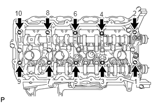


d.
A160684E08
2.823,1.646 2.938,1.802 0.115,0.156 10 true 1 2.802,0.198 2.917,0.354 0.115,0.156 10 true 2 2.125,1.646 2.24,1.802 0.115,0.156 10 true 3 2.104,0.219 2.219,0.375 0.115,0.156 10 true 4 1.563,1.646 1.677,1.802 0.115,0.156 10 true 5 1.552,0.208 1.667,0.365 0.115,0.156 10 false 6 0.99,1.646 1.104,1.802 0.115,0.156 10 true 7 0.969,0.188 1.083,0.344 0.115,0.156 10 false 8 0.365,1.646 0.479,1.802 0.115,0.156 10 true 9 0.313,0.198 0.5,0.354 0.188,0.156 10 false 10

Tighten the 10 bolts in the order shown in the illustration.

Torque:
16 N*m (163 kgf*cm, 12 ft.*lbf)

NOTICE:

Thoroughly wipe clean any seal packing.


Hide 13550 5.INSTALL NO. 2 CHAIN TENSIONER ASSEMBLY
a.
A148228E09
1.406,2.677 1.531,2.875 false 2.063,2.635 2.802,2.635 false 2.802,1.698 2.802,2.875 false 2.469,0.927 2.906,1.302 0.438,0.375 10 true Push 2.688,2.906 2.927,3.073 0.24,0.167 10 false Pin 1.24,2.885 1.74,3.052 0.5,0.167 10 false Plunger

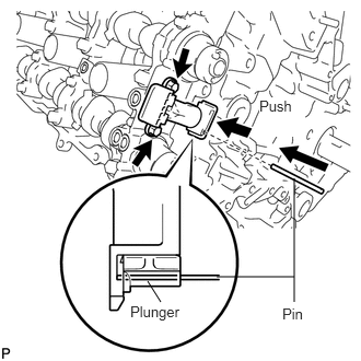
Install the chain tensioner with the 2 bolts.

Torque:
10 N*m (102 kgf*cm, 7 ft.*lbf)


b.

While raising up the No. 2 chain tensioner, insert a pin of φ1.0 mm (0.0394 in.) into the hole to fix it in place.


Hide 13506 6.INSTALL CHAIN SUB-ASSEMBLY (for RH Side)
a.
A198566E05
1.781,0.219 1.979,0.219 1.979,0.219 2.385,0.604 false 2.375,0.708 2.375,1.208 false 0.906,0.115 1.646,0.323 0.74,0.208 10 false Mark Plate 1.958,1.208 2.813,1.417 0.854,0.208 10 true Timing Mark

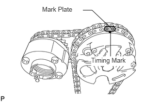
Align the No. 1 chain's orange mark plate with the camshaft timing gear's timing mark, and attach the chain to the gear as shown in the illustration.

b.
A149461E11
2.365,1.708 1.969,1.844 true 1.885,1.771 1.125,1.615 true 0.271,1.521 1.063,1.698 0.792,0.177 10 false Timing Mark 2.438,1.646 3.156,1.813 0.719,0.167 10 false Mark Plate

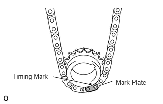
Align the No. 1 chain's orange mark plate with the crankshaft timing gear's timing mark, and attach the chain to the gear as shown in the illustration.

c.
A160663E10
0.854,1.115 1.979,1.885 1.979,1.885 2.75,1.115 true 0.875,0.75 1.188,0.135 1.188,0.135 1.323,0.135 false 2.375,0.146 2.521,0.146 2.521,0.146 2.729,0.813 false 1.594,1.927 2.333,2.094 0.74,0.167 10 false Mark Plate 1.438,0.063 2.292,0.26 0.854,0.198 10 false Timing Mark

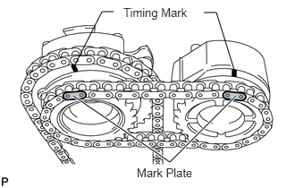
Align the No. 2 chain's mark plates (yellow) with the timing marks of the camshaft timing gear and camshaft timing exhaust gear, and attach the No. 2 chain to the gears as shown in the illustration.

NOTICE:

The camshaft timing exhaust gear has 2 grooves. Align the mark plates of the No. 2 chain with the first groove.


HINT:

The crankshaft timing gear and camshaft exhaust gear will be installed with the No. 1 and No. 2 chains connected to the gears.


d.

Install the crankshaft timing sprocket to the crankshaft.


e.

Align and attach the knock pin of the No. 1 camshaft with the pin hole of the camshaft timing gear.


f.

Using the hexagonal portion of the No. 2 camshaft, align and attach the knock pin of the No. 2 camshaft with the pin hole of the camshaft timing exhaust gear.


g.

Remove the pin from the No. 2 chain tensioner.


h.

Using a wrench to hold the hexagonal portion of the No. 1 camshaft, temporarily install the bolt.


i.

Using a wrench to hold the hexagonal portion of the No. 2 camshaft, temporarily install the bolt.


Hide 13561 7.INSTALL NO. 1 CHAIN VIBRATION DAMPER (for RH Side)
a.
A160658

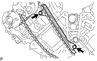
Install the vibration damper with the 2 bolts.

Torque:
21 N*m (214 kgf*cm, 15 ft.*lbf)


Hide 13559 8.INSTALL CHAIN TENSIONER SLIPPER (for RH Side)
A178486

HINT:

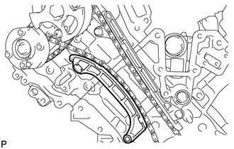
If you cannot install the chain tensioner slipper due to the tension of the chain, use the hexagonal portion of the camshaft to loosen the chain, and then install the chain tensioner slipper.


Hide 13540 9.INSTALL NO. 1 CHAIN TENSIONER ASSEMBLY (for RH Side)
a.
A148260E02
2.77,1.572 3.313,1.756 0.543,0.184 10 Plunger 0.066,0.38 0.939,0.569 0.873,0.188 10 Stopper Plate 1.159,0.477 1.485,0.477 1.485,0.477 2.005,0.931 false 1.393,1.37 1.393,0.477 false 1.87,1.657 2.74,1.657 false 2.435,1.029 2.435,1.657 false

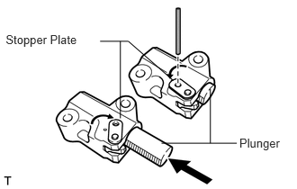
Move the stopper plate upward to release the lock, and push the plunger deep into the tensioner.


b.

Move the stopper plate downward to set the lock, and insert a hexagon wrench into the hole of the stopper plate.

c.
A150146

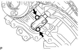
Install the chain tensioner with the 2 bolts.

Torque:
10 N*m (102 kgf*cm, 7 ft.*lbf)


d.

Remove the hexagon wrench from the chain tensioner.


Hide 13560A 10.INSTALL NO. 3 CHAIN TENSIONER ASSEMBLY
a.
A148227E06
1.99,1.802 1.875,1.802 1.875,1.802 1.813,2.188 false 1.292,2.542 1.979,2.365 false 2.479,0.333 3.021,0.583 0.542,0.25 10 true Push 2.052,1.729 2.292,1.896 0.24,0.167 10 false Pin 0.719,2.448 1.281,2.656 0.563,0.208 10 false Plunger

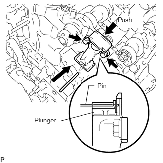
Install the chain tensioner with the 2 bolts.

Torque:
10 N*m (102 kgf*cm, 7 ft.*lbf)


b.

While pushing down the No. 2 chain tensioner, insert a pin of φ1.0 mm (0.0394 in.) into the hole to fix it in place.


Hide 13506 11.INSTALL CHAIN SUB-ASSEMBLY (for LH Side)
a.
A198567E05
1.094,0.656 1.406,0.188 1.406,0.188 1.604,0.188 true 1.104,0.74 1.104,1.167 true 1.646,0.104 2.385,0.302 0.74,0.198 10 false Mark Plate 0.656,1.167 1.51,1.375 0.854,0.208 10 true Timing Mark

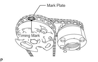
Align the No. 1 chain's orange mark plate with the camshaft timing gear's timing mark, and attach the chain to the gear as shown in the illustration.

b.
A149462E12
2.333,1.563 1.813,1.698 true 1.677,1.479 1.115,1.427 true 0.271,1.333 1.063,1.51 0.792,0.177 10 false Timing Mark 2.365,1.479 3.083,1.646 0.719,0.167 10 false Mark Plate

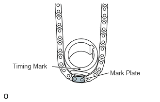
Align the No. 1 chain's orange mark plate with the crankshaft timing gear's timing mark, and attach the chain to the gear as shown in the illustration.
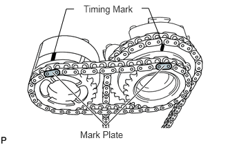

c.
A160666E10
0.813,0.802 1,0.135 1,0.135 1.115,0.135 false 2.135,0.125 2.24,0.125 2.24,0.125 2.458,0.677 false 0.792,1.094 1.594,1.896 1.594,1.896 2.479,0.99 true 1.26,0.052 2.094,0.26 0.833,0.208 10 false Timing Mark 1.208,1.948 1.979,2.125 0.771,0.177 10 false Mark Plate

Align the No. 2 chain's mark plates (yellow) with the timing marks of the camshaft timing gear and camshaft timing exhaust gear, and attach the No. 2 chain to the gears as shown in the illustration.

NOTICE:

The camshaft timing exhaust gear has 2 grooves. Align the mark plates of the No. 2 chain with the first groove.


HINT:

The crankshaft timing gear and camshaft exhaust gear will be installed with the No. 1 and No. 2 chains connected to the gears.


d.

Install the crankshaft timing sprocket to the crankshaft.


e.

Align and attach the knock pin of the No. 3 camshaft with the pin hole of the camshaft timing gear.


f.

Using the hexagonal portion of the No. 4 camshaft, align and attach the knock pin of the No. 4 camshaft with the pin hole of the camshaft timing exhaust gear.

NOTICE:

Because the gears' timing mark positions may shift due to looseness of the No. 1 chain, use the hexagonal portion of the camshaft to hold the No. 3 camshaft in place until the No. 1 chain tensioner is installed.


g.

Remove the pin from the No. 3 chain tensioner.


h.

Using a wrench to hold the hexagonal portion of the No. 3 camshaft, temporarily install the bolt.


i.

Using a wrench to hold the hexagonal portion of the No. 4 camshaft, temporarily install the bolt.


Hide 13559 12.INSTALL CHAIN TENSIONER SLIPPER (for LH Side)
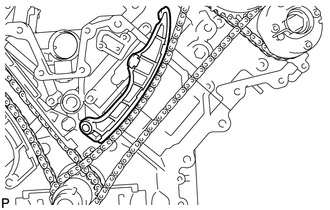
A178487

HINT:

If you cannot install the chain tensioner slipper due to the tension of the chain, use the hexagonal portion of the camshaft to loosen the chain and install the chain tensioner.


Hide 13540 13.INSTALL NO. 1 CHAIN TENSIONER ASSEMBLY (for LH Side)
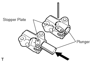
a.
A148260E01
2.712,1.388 3.255,1.572 0.543,0.184 10 Plunger 0.1,0.606 0.973,0.794 0.873,0.188 10 Stopper Plate 2.425,1.1 2.682,1.467 2.682,1.467 1.951,1.72 false 1.996,0.979 1.174,0.693 1.174,0.693 1.361,1.403 false

Move the stopper plate upward to release the lock, and push the plunger deep into the tensioner.


b.

Move the stopper plate downward to set the lock, and insert a hexagon wrench into the hole of the stopper plate.
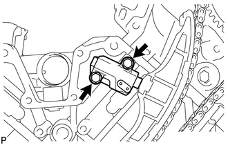

c.
A160733

Install a new gasket and the chain tensioner with the 2 bolts.

Torque:
10 N*m (102 kgf*cm, 7 ft.*lbf)


Hide 13561 14.INSTALL NO. 1 CHAIN VIBRATION DAMPER (for LH Side)
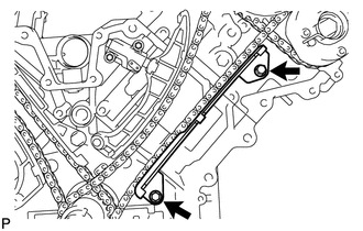
a.
A178533

Install the vibration damper with the 2 bolts.

Torque:
21 N*m (214 kgf*cm, 15 ft.*lbf)


b.

Remove the hexagon wrench from the No. 1 chain tensioner.


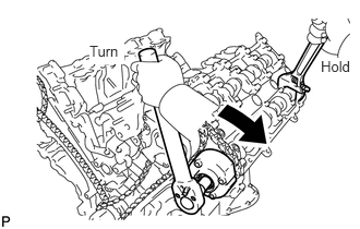
Hide 13050 15.TIGHTEN CAMSHAFT TIMING GEAR ASSEMBLY (for LH Side)
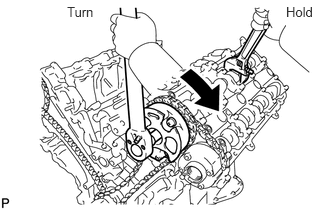
a.
A161993E03
2.979,0.042 3.323,0.333 0.344,0.292 10 true Hold 0.698,0.042 1.042,0.229 0.344,0.188 10 false Turn

Using a wrench to hold the hexagonal portion of the No. 3 camshaft, tighten the camshaft timing gear with the bolt.

Torque:
100 N*m (1020 kgf*cm, 74 ft.*lbf)


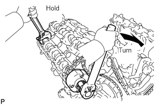
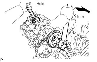
b.
A161994E03
0.854,0.406 1.188,0.615 0.333,0.208 10 true Turn 3.063,0.552 3.385,0.792 0.323,0.24 10 true Hold

Using a wrench to hold the hexagonal portion of the No. 4 camshaft, tighten the camshaft timing exhaust gear with the bolt.

Torque:
100 N*m (1020 kgf*cm, 74 ft.*lbf)


Hide 13050 16.TIGHTEN CAMSHAFT TIMING GEAR ASSEMBLY (for RH Side)
a.
A161995E03
2.698,0.5 3.094,0.896 0.396,0.396 10 true Turn 1.292,0.042 1.646,0.25 0.354,0.208 10 false Hold

Using a wrench to hold the hexagonal portion of the No. 1 camshaft, tighten the camshaft timing gear with the bolt.

Torque:
100 N*m (1020 kgf*cm, 74 ft.*lbf)


b.
A161996E03
2.469,0.958 2.865,1.333 0.396,0.375 10 true Turn 0.958,0.083 1.292,0.438 0.333,0.354 10 true Hold

Using a wrench to hold the hexagonal portion of the No. 2 camshaft, tighten the camshaft timing exhaust gear with the bolt.

Torque:
100 N*m (1020 kgf*cm, 74 ft.*lbf)


Hide 17.CHECK NO. 1 CYLINDER TO TDC/COMPRESSION

a.

Temporarily install the pulley set bolt.


b.

Rotate the crankshaft clockwise, and check that the timing marks on the crankshaft timing gear and camshaft timing gears are as shown in the illustration.
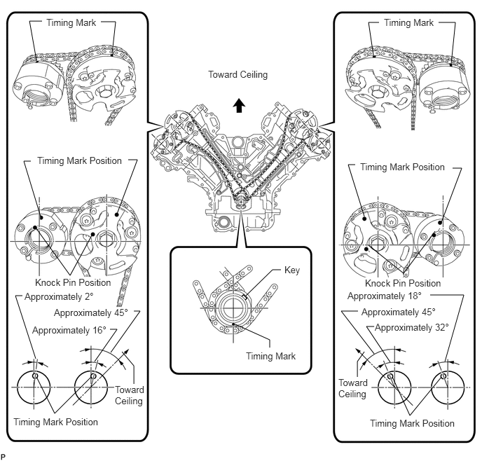
A160654E07
3.479,4.813 4.01,5.052 4.01,5.052 4.01,5.167 false 3.656,4.396 4.052,4.01 4.052,4.01 4.177,4.01 false 0.625,0.313 0.438,0.313 0.438,0.313 0.542,0.896 false 1.5,0.323 1.719,0.323 1.719,0.323 1.667,0.792 false 5.635,0.333 5.479,0.333 5.479,0.333 5.552,0.823 false 6.521,0.333 6.771,0.333 6.771,0.333 6.708,0.948 false 0.542,5.604 0.813,6.146 0.813,6.146 1.354,5.604 false 0.333,4.396 0.229,4.396 0.229,4.396 0.531,5.333 false 0.531,3.385 1.042,4.094 1.042,4.094 1.375,3.479 false 5.833,5.604 6.094,6.177 6.094,6.177 6.563,5.604 false 5.323,4.625 5.073,4.625 5.073,4.625 5.563,5.26 false 6.385,4.385 6.896,4.385 6.896,4.385 6.615,5.375 false 5.479,3.646 6,4.063 6,4.063 6.469,3.438 false 0.604,3.219 0.354,2.396 0.354,2.396 0.458,2.396 false 1.74,3.177 2.042,2.375 2.042,2.375 1.906,2.375 false 5.417,3.219 5.177,2.448 5.177,2.448 5.281,2.448 false 6.563,3.302 6.865,2.5 6.865,2.5 6.729,2.5 false 1.406,5.375 1.74,4.896 1.74,4.896 1.635,4.896 false 1.646,5.24 2.083,4.625 2.083,4.625 1.99,4.625 false 1.813,5.229 1.99,5.438 1.99,5.438 1.99,5.708 false 5.417,5.229 5.313,5.375 5.313,5.375 5.313,5.604 false 5.563,4.854 5.448,4.854 5.448,4.854 5.802,5.385 false 3.656,5.208 4.51,5.375 0.854,0.167 10 false Timing Mark 4.229,3.927 4.542,4.125 0.313,0.198 10 false Key 0.688,0.25 1.521,0.427 0.833,0.177 10 false Timing Mark 5.708,0.25 6.542,0.427 0.833,0.177 10 false Timing Mark 0.198,6.188 1.573,6.396 1.375,0.208 10 false Timing Mark Position 0.521,4.115 1.771,4.323 1.25,0.208 10 true Knock Pin Position 5.375,4.552 6.604,4.802 1.229,0.25 10 true Approximately 45° 5.573,4.781 6.698,4.979 1.125,0.198 10 true Approximately 32° 5.5,6.208 6.875,6.417 1.375,0.208 10 false Timing Mark Position 5.427,4.125 6.677,4.333 1.25,0.208 10 true Knock Pin Position 0.552,2.302 1.927,2.479 1.375,0.177 10 false Timing Mark Position 5.354,2.396 6.729,2.573 1.375,0.177 10 false Timing Mark Position 0.365,4.323 1.594,4.573 1.229,0.25 10 true Approximately 2° 0.479,4.823 1.708,5.073 1.229,0.25 10 false Approximately 16° 0.802,4.563 1.948,4.76 1.146,0.198 10 true Approximately 45° 1.708,5.708 2.198,6.083 0.49,0.375 10 false Toward Ceiling 5.031,5.604 5.521,5.979 0.49,0.375 10 false Toward Ceiling 5.167,4.313 6.396,4.563 1.229,0.25 10 true Approximately 18° 3.094,1.021 4.115,1.396 1.021,0.375 10 false Toward Ceiling


c.

Remove the crankshaft pulley bolt.


Hide 11302 18.INSTALL TIMING CHAIN COVER SUB-ASSEMBLY

a.

Install the timing chain cover (See page Engine / Hybrid System>3UR-FBE LUBRICATION>OIL PUMP>INSTALLATION).