3UR-FE ENGINE MECHANICAL CAMSHAFT INSPECTION
PROCEDURE

 13050
1.INSPECT CAMSHAFT TIMING GEAR ASSEMBLY
Install the camshafts (See page Engine / Hybrid System>3UR-FE ENGINE MECHANICAL>CAMSHAFT>REMOVAL).
- HINT:
-
Only install the intake camshaft.
Install the camshaft housing (See page Engine / Hybrid System>3UR-FE ENGINE MECHANICAL>CAMSHAFT>REMOVAL).
Apply a light coat of engine oil on the camshaft and camshaft timing gear.
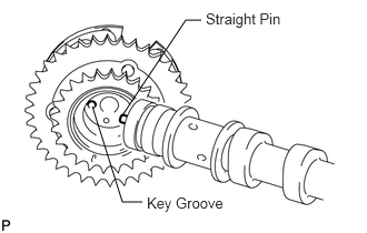
Using the hexagonal portion of the camshaft, align and attach the knock pin of the camshaft with the pin hole of the camshaft timing gear.
- NOTICE:
- ·
Do not forcefully push in the camshaft timing gear. This may cause the camshaft knock pin tip to damage the installation surface of the camshaft timing gear.
·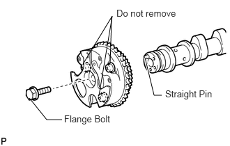 0.438,1.469 0.698,1.792 0.698,1.792 0.927,1.792 false 2.167,0.865 2.302,1.427 2.302,1.427 2.417,1.427 true 1.479,1.427 1.677,0.24 false 1.646,0.948 1.667,0.26 false 1.24,0.958 1.677,0.24 false 2.469,1.323 3.219,1.51 0.75,0.188 10 false Straight Pin 1.74,0.115 2.771,0.302 1.031,0.188 10 false Do not remove 0.958,1.698 1.698,1.875 0.74,0.177 10 false Flange Bolt
Do not loosen or remove the 3 bolts shown in the illustration. If any of them are loosened or removed, the backlash of the gear in the timing tube will go out of adjustment. In this case, replace the camshaft timing gear assembly with a new one.
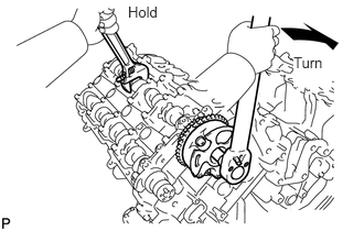
Apply a light coat of engine oil on the threads and under the head of the bolt.
Using a wrench to hold the hexagonal portion of the camshaft, install the camshaft timing gear with the bolt.
- Torque:
- 100 N*m (1020 kgf*cm, 74 ft.*lbf)
Remove the camshaft bearing cap (See page Engine / Hybrid System>3UR-FE ENGINE MECHANICAL>CAMSHAFT>REMOVAL).
Check the lock of the camshaft timing gear.
Clamp the camshaft in a vise, and confirm that the camshaft timing gear is locked.
- NOTICE:
-
Be careful not to damage the camshaft.
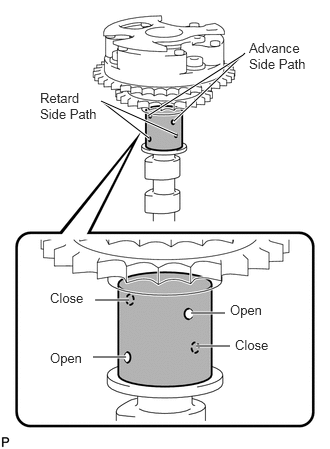
Release the lock pin.
Cover the 4 oil paths of the cam journal with vinyl tape as shown in the illustration.
Break through the tape of the advance side path. Then break through the tape of the retard side path on the opposite side of the advanced side path, as shown in the illustration.
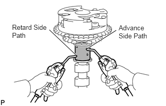
Apply approximately 200 kPa (2.0 kgf/cm2, 29 psi) of air pressure to the two broken paths.
- NOTICE:
-
Cover the paths with a piece of cloth when applying pressure to keep oil from splashing.
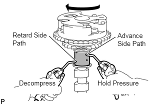
Check that the camshaft timing gear revolves in the advance direction when reducing the air pressure applied to the retard side path.
- HINT:
-
This operation releases the lock pin for the most retarded position.
When the camshaft timing gear reaches the most advanced position, release the air pressure from the retard side path and advance side path, in that order.
- NOTICE:
-
Do not release the air pressure from the advance side path first. The gear may abruptly shift in the retard direction and break the lock pin.
Check for smooth rotation.
Turn the camshaft timing gear within its movable range (21°) 2 or 3 times, but do not turn it to the most retarded position. Make sure that the gear turns smoothly.
- NOTICE:
-
Do not use air pressure to perform the smooth rotation check.
Check the lock in the most retarded position.
Confirm that the camshaft timing gear is locked at the most retarded position.
Install the camshaft bearing cap (See page Engine / Hybrid System>3UR-FE ENGINE MECHANICAL>CAMSHAFT>INSTALLATION).
- HINT:
-
Only install the intake camshaft.
Install the camshaft housing (See page Engine / Hybrid System>3UR-FE ENGINE MECHANICAL>CAMSHAFT>INSTALLATION).
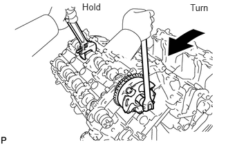
Hold the hexagonal portion of the camshaft with a wrench and loosen the bolt.
Remove the camshafts (See page Engine / Hybrid System>3UR-FE ENGINE MECHANICAL>CAMSHAFT>INSTALLATION).
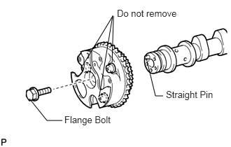
Remove the flange bolt and camshaft timing gear.
13080
2.INSPECT AND ADJUST CAMSHAFT TIMING EXHAUST GEAR ASSEMBLY
Install the camshafts (See page Engine / Hybrid System>3UR-FE ENGINE MECHANICAL>CAMSHAFT>REMOVAL).
- HINT:
-
Only install the exhaust camshaft.
Install the camshaft housing (See page Engine / Hybrid System>3UR-FE ENGINE MECHANICAL>CAMSHAFT>REMOVAL).
Apply a light coat of engine oil on the camshaft and camshaft timing exhaust gear.
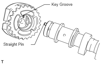
Using the hexagonal portion of the camshaft, align and attach the knock pin of the camshaft with the pin hole of the camshaft timing exhaust gear.
- NOTICE:
- ·
Do not forcefully push in the camshaft timing exhaust gear. This may cause the camshaft knock pin tip to damage the installation surface of the camshaft timing exhaust gear.
·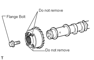 0.948,1.208 1.375,0.417 1.375,0.417 1.177,1.26 true 0.979,1.646 1.208,1.854 1.208,1.854 1.646,1.854 true 1.188,1.698 1.208,1.844 true 0.208,0.583 0.073,0.583 0.073,0.583 0.344,1.542 false 1.417,0.292 2.438,0.469 1.021,0.177 10 false Do not remove 1.656,1.74 2.677,1.917 1.021,0.177 10 false Do not remove 0.24,0.521 1.042,0.75 0.802,0.229 10 false Flange Bolt
Do not loosen or remove the 4 bolts shown in the illustration. If any of them are loosened or removed, the backlash of the gear in the timing tube will go out of adjustment. In this case, replace the camshaft timing exhaust gear assembly with a new one.
Apply a light coat of engine oil on the threads and under the head of the bolt.
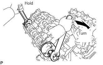
Using a wrench to hold the hexagonal portion of the camshaft, install the camshaft timing exhaust gear with the bolt.
- Torque:
- 100 N*m (1020 kgf*cm, 74 ft.*lbf)
Remove the camshaft bearing cap (See page Engine / Hybrid System>3UR-FE ENGINE MECHANICAL>CAMSHAFT>REMOVAL).
Check the camshaft timing exhaust gear lock.
Make sure that the camshaft timing exhaust gear is locked.
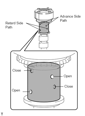
Release the lock pin.
Cover the 4 oil paths of the cam journal with vinyl tape as shown in the illustration.
Break through the tape of the advance side path. Then break through the tape of the retard side path on the opposite side of the advanced side path, as shown in the illustration.
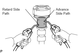
Apply approximately 200 kPa (2.0 kgf/cm2, 29 psi) of air pressure to the two broken paths (the advance side path and the retard side path).
- NOTICE:
-
Cover the paths with a piece of cloth when applying pressure to keep oil from splashing.
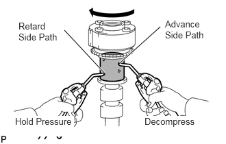
Check that the camshaft timing exhaust gear turns in the retard direction when reducing the air pressure applied to the advance side path.
- HINT:
-
The lock pin is released and the camshaft timing exhaust gear turns in the retard direction.
When the camshaft timing exhaust gear moves to the most retarded position, release the air pressure from the advance side path, and then release the air pressure from the retard side path.
- NOTICE:
-
Be sure to release the air pressure from the advance side path first. If the air pressure of the retard side path is released first, the camshaft timing exhaust gear may abruptly shift in the advance direction and break the lock pin or other parts.
Check for smooth rotation.
Turn the camshaft timing exhaust gear within its movable range (18.5°) 2 or 3 times, but do not turn it to the most advanced position. Make sure that the gear turns smoothly.
- NOTICE:
-
When the air pressure is released from the advance side path and then from the retard side path, the gear automatically returns to the most advanced position due to the advance assist spring operation, and locks. Gradually release the air pressure from the retard side path before performing the smooth rotation check.
Check the lock at the most advanced position.
Make sure that the camshaft timing exhaust gear is locked at the most advanced position.
Install the camshaft bearing cap (See page Engine / Hybrid System>3UR-FE ENGINE MECHANICAL>CAMSHAFT>INSTALLATION).
- HINT:
-
Only install the exhaust camshaft.
Install the camshaft housing (See page Engine / Hybrid System>3UR-FE ENGINE MECHANICAL>CAMSHAFT>INSTALLATION).
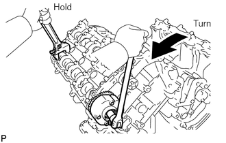
Hold the hexagonal portion of the camshaft with a wrench and loosen the bolt.
Remove the camshafts (See page Engine / Hybrid System>3UR-FE ENGINE MECHANICAL>CAMSHAFT>INSTALLATION).
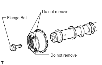
Remove the flange bolt and camshaft timing exhaust gear.