3UR-FBE COOLING THERMOSTAT INSTALLATION
PROCEDURE

 16031
1.INSTALL WATER INLET SUB-ASSEMBLY WITH THERMOSTAT
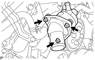
Install a new gasket and the water inlet with thermostat with the 3 nuts.
- Torque:
- 10 N*m (102 kgf*cm, 7 ft.*lbf)
16281F
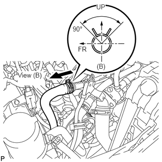
2.CONNECT NO. 5 WATER BY-PASS HOSE
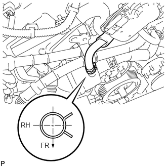
Connect the No. 5 water by-pass hose.
- HINT:
-
Install the hose so that the direction of the hose clamp is as indicated in the illustration.
16572
3.CONNECT OUTLET RADIATOR HOSE
17303
4.INSTALL AIR PIPE SUB-ASSEMBLY
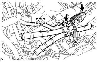
Install the air pipe with the bolt.
- Torque:
- 10 N*m (102 kgf*cm, 7 ft.*lbf)
Connect the connector and install the wire harness with the 2 clamps.
17342
5.CONNECT NO. 2 AIR INJECTION SYSTEM HOSE
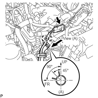
Connect the No. 2 air injection hose.
Attach the wire harness clamp.
Connect the air pump connector.
17343
6.CONNECT NO. 3 AIR INJECTION SYSTEM HOSE
Connect the No. 3 air injection hose.
7.ADD ENGINE COOLANT
8.INSPECT FOR COOLANT LEAK
11209
9.INSTALL V-BANK COVER SUB-ASSEMBLY
51441
10.INSTALL NO. 1 ENGINE UNDER COVER