Home › Drivetrain › AB60F AUTOMATIC TRANSMISSION / TRANSAXLE › AUTOMATIC TRANSMISSION SYSTEM
RM27L0U _52 Drivetrain _049310 AB60F AUTOMATIC TRANSMISSION / TRANSAXLE _0235644 AUTOMATIC TRANSMISSION SYSTEM J

AB60F AUTOMATIC TRANSMISSION / TRANSAXLE  AUTOMATIC TRANSMISSION SYSTEM  Pattern Select Switch Circuit  


DESCRIPTION

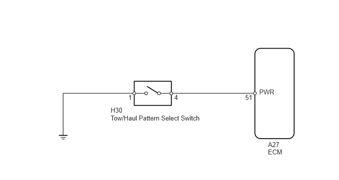
The ECM receives tow/haul pattern select switch information and performs the tow/haul control.

While the tow/haul control is operating, in contrast to normal mode, low gears are used to increase engine braking and towing power, reduce frequent shifts, and improve driveability. The tow/haul control includes throttle control, shift schedule control, wide open throttle shift timing control and AI-SHIFT control.

Tow/haul mode only operates when the shift lever is in D and the tow/haul pattern select switch is ON.

HINT:
·

The tow/haul pattern select switch is a momentary-type switch.

·

In order to cancel tow/haul mode, push the tow/haul pattern select switch again or turn the ignition switch off.


WIRING DIAGRAM
C179317E01
5.665,2.979 6.034,3.149 0.369,0.170 10 A27 5.665,3.132 6.087,3.327 0.422,0.195 10 ECM 2.338,2.245 2.862,2.440 0.524,0.195 10 H30 2.338,2.419 4.602,2.614 2.265,0.195 10 Tow/Haul Pattern Select Switch 2.711,1.977 2.897,2.172 0.186,0.195 10 1 3.683,1.977 3.869,2.172 0.186,0.195 10 4 5.184,1.977 5.370,2.172 0.186,0.195 10 51 5.481,1.86 5.885,2.055 0.404,0.195 10 PWR

PROCEDURE

1.INSPECT TOW/HAUL PATTERN SELECT SWITCH ASSEMBLY
a.
C162988E02
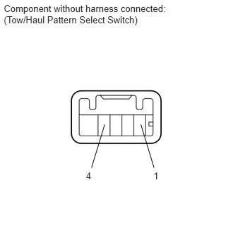
0.056,0.045 2.587,0.412 2.531,0.367 10 Component without harness connected: (Tow/Haul Pattern Select Switch) 2.264,2.51 2.442,2.655 0.178,0.145 10 1 1.268,2.51 1.433,2.655 0.164,0.145 10 4 1.544,1.836 1.35,2.474 false 2.078,1.836 2.272,2.474 false

Remove the tow/haul pattern select switch.


b.

Measure the resistance according to the value(s) in the table below.

Standard Resistance:
Tester Connection Switch Condition Specified Condition
1 - 4 Tow/haul pattern select switch ON Below 1 Ω
Tow/haul pattern select switch OFF 10 kΩ or higher


OK

2.CHECK HARNESS AND CONNECTOR (TOW/HAUL PATTERN SELECT SWITCH - BODY GROUND)

NG

REPLACE TOW/HAUL PATTERN SELECT SWITCH ASSEMBLY

2.CHECK HARNESS AND CONNECTOR (TOW/HAUL PATTERN SELECT SWITCH - BODY GROUND)
a.
U153550E01
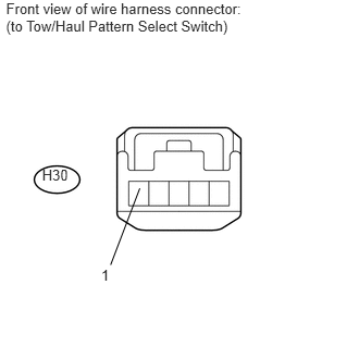
0.058,0.005 2.467,0.372 2.409,0.367 10 Front view of wire harness connector: (to Tow/Haul Pattern Select Switch) 1.059,2.536 1.338,1.803 false 0.969,2.551 1.172,2.753 0.203,0.202 10 1 0.403,1.589 0.778,1.822 0.375,0.233 10 H30

Disconnect the H30 tow/haul pattern select switch connector.


b.

Measure the resistance according to the value(s) in the table below.

Standard Resistance:
Tester Connection Condition Specified Condition
H30-1 - Body ground Always Below 1 Ω


OK

3.CHECK HARNESS AND CONNECTOR (TOW/HAUL PATTERN SELECT SWITCH - ECM)

NG

REPAIR OR REPLACE HARNESS OR CONNECTOR

3.CHECK HARNESS AND CONNECTOR (TOW/HAUL PATTERN SELECT SWITCH - ECM)
a.
U153487E01
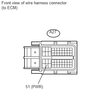
0.052,0.006 2.461,0.373 2.409,0.367 10 Front view of wire harness connector: (to ECM) 1.681,1.001 2.056,1.234 0.375,0.233 10 A27 0.869,2.867 1.556,3.069 0.687,0.202 10 51 (PWR) 1.296,2.852 1.605,2.196 false

Disconnect the A27 ECM connector.


b.

Measure the resistance according to the value(s) in the table below.

Standard Resistance:
Tester Connection Switch Condition Specified Condition
A27-51 (PWR) - Body ground Tow/haul pattern select switch ON Below 1 Ω
Tow/haul pattern select switch OFF 10 kΩ or higher


OK

PROCEED TO NEXT SUSPECTED AREA SHOWN IN PROBLEM SYMPTOMS TABLE

NG

REPAIR OR REPLACE HARNESS OR CONNECTOR