AB60F AUTOMATIC TRANSMISSION / TRANSAXLE SHIFT LEVER INSPECTION
PROCEDURE

 1.INSPECT SHIFT LOCK CONTROL ECU
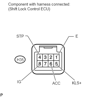
Measure the voltage according to the value(s) in the table below.
- HINT:
-
Measure the voltage of the connector.
- Standard Voltage:
Tester Connection Switch Condition Specified Condition H35-5 (KLS+) - H35-1 (E) Ignition switch ACC and shift lever on P Below 1 V H35-5 (KLS+) - H35-1 (E) Ignition switch ACC and shift lever not on P 7.5 to 11 V H35-5 (KLS+) - H35-1 (E) Ignition switch ACC and shift lever not on P (after approx. 1 second) 6 to 9 V H35-6 (ACC) - H35-1 (E) Ignition switch ON 10 to 14 V H35-6 (ACC) - H35-1 (E) Ignition switch ACC 10 to 14 V H35-6 (ACC) - H35-1 (E) Ignition switch OFF Below 1 V H35-4 (STP) - H35-1 (E) Brake pedal depressed 10 to 14 V H35-4 (STP) - H35-1 (E) Brake pedal released Below 1 V H35-8 (IG) - H35-1 (E) Ignition switch ON 10 to 14 V H35-8 (IG) - H35-1 (E) Ignition switch OFF Below 1 V
If the result is not as specified, replace the shift lock control ECU.
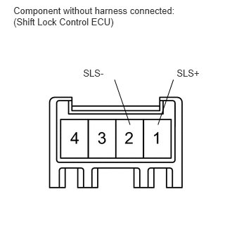
Disconnect the shift lock solenoid connector from the shift lock control ECU.
Measure the voltage according to the values in the table below.
- HINT:
-
Do not disconnect the shift lock control ECU connector.
- Standard Voltage:
Tester Connection Switch Condition Specified Condition 1 (SLS+) - 2 (SLS-) Ignition switch OFF Below 1 V 1 (SLS+) - 2 (SLS-) Ignition switch ON Below 1 V 1 (SLS+) - 2 (SLS-) Ignition switch ON and brake pedal depressed 11 to 14 V
If the result is not as specified, replace the shift lock control ECU.
2.INSPECT SHIFT LOCK SOLENOID
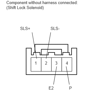
Disconnect the shift lock solenoid connector from the shift lock control ECU.
Measure the resistance according to the values in the table below.
- Standard Resistance:
Tester Connection Condition Specified Condition 1 (SLS+) - 2 (SLS-) When battery voltage not applied 101 to 123 Ω 3 (E2) - 4 (P) Shift position P 10 kΩ or higher 3 (E2) - 4 (P) Shift position not P Below 1 Ω
If the result is not as specified, replace the transmission floor shift assembly.
Apply 12 V battery voltage to the shift lock solenoid valve and check that the valve moves and makes an operating noise.
- OK:
Measurement Condition Specified Condition Battery positive (+) → Terminal 1 (SLS+)
Battery negative (-) → Terminal 2 (SLS-)Solenoid moves and makes an operating noise
If the result is not as specified, replace the transmission floor shift assembly.
84722
3.INSPECT TRANSMISSION CONTROL SWITCH
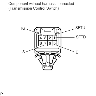
Measure the resistance according to the value(s) in the table below.
- Standard Resistance:
Tester Connection Condition Specified Condition 3 (IG) - 7 (S) Shift position S Below 1 Ω 3 (IG) - 7 (S) Shift position not S 10 kΩ or higher 2 (SFTU) - 5 (E) Shift lever continuously shifted to "+" position (Up-shift) Below 1 Ω 2 (SFTU) - 5 (E) Shift lever S position 10 kΩ or higher 1 (SFTD) - 5 (E) Shift lever continuously shifted to "-" position (Down-shift) Below 1 Ω 1 (SFTD) - 5 (E) Shift position S 10 kΩ or higher
If the result is not as specified, replace the transmission floor shift assembly.