DRIVE SHAFT / PROPELLER SHAFT PROPELLER SHAFT ASSEMBLY(for 4WD) REASSEMBLY
PROCEDURE

 04371H
1.INSTALL REAR PROPELLER SHAFT UNIVERSAL JOINT SPIDER
- HINT:
-
Use the same installation procedure for both the front and rear propeller shaft universal joint spiders.
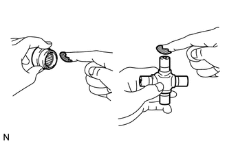
Apply MP grease to a new universal joint spider and universal joint spider bearings.
- NOTICE:
-
Be careful not to apply too much grease.
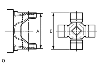
Measure dimension A between the snap ring grooves.
Install the universal joint spider bearing into the universal joint spider and measure dimension B.
- HINT:
-
When measuring dimension B, clamp the universal joint spider and universal joint spider bearing in a vise to hold them together.
Select hole snap rings of the correct thickness to make dimensions A and B the same.
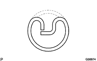
w/o Grease Fitting Spider Bearing:
- Hole Snap Ring Thickness:
Color Thickness Purple 1.46 mm (0.0574 in.) Black 1.49 mm (0.0586 in.) Copper 1.51 mm (0.0594 in.) Black 1.52 mm (0.0598 in.) Black 1.54 mm (0.0606 in.) White 1.56 mm (0.0614 in.) Black 1.57 mm (0.0618 in.) Yellow 1.59 mm (0.0625 in.) Black 1.62 mm (0.0638 in.) Blue 1.64 mm (0.0646 in.)
- NOTICE:
- ·
Use new hole snap rings.
·If possible, use hole snap rings of the same thickness for both edges.

w/ Grease Fitting Spider Bearing:
- Hole Snap Ring Thickness:
Color Thickness Black 1.49 mm (0.0586 in.) Copper 1.51 mm (0.0594 in.) White 1.56 mm (0.0614 in.) Yellow 1.59 mm (0.0625 in.)
- NOTICE:
- ·
Use new hole snap rings.
·If possible, use hole snap rings of the same thickness for both edges.
Temporarily install the universal joint spider and 2 universal joint spider bearings into the universal joint sleeve yoke.
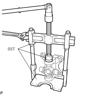
Using SST, press the universal joint spider bearing into the universal joint sleeve yoke until the groove can be seen.
- SST
- 09950-40011 (09951-04020, 09952-04010, 09953-04020, 09954-04020, 09955-04051, 09957-04010)
09950-60010 (09951-00290)
09336-16010
- NOTICE:
-
Confirm that the universal joint spider moves smoothly while pressing it in.
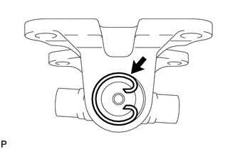
Using needle-nose pliers, install a hole snap ring into the groove on the universal joint sleeve yoke.
- HINT:
-
Use the same installation procedure for the universal joint spider bearing on the opposite side.
Temporarily install the universal joint spider and 2 universal joint spider bearings into the propeller shaft's universal joint yoke.
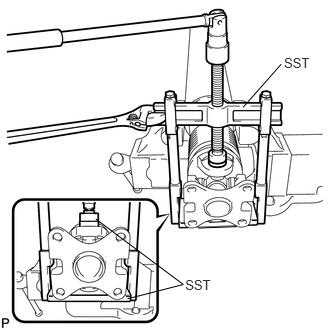
Using SST, press the universal joint spider bearing into the universal joint yoke until the groove can be seen.
- SST
- 09950-40011 (09951-04020, 09952-04010, 09953-04020, 09954-04020, 09955-04051, 09957-04010)
09950-60010 (09951-00290)
09336-16010
- NOTICE:
- ·
Position SST (09336-16010) so that the cutout faces the propeller shaft tube.
·Confirm that the universal joint spider moves smoothly while pressing it in.
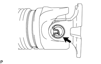
Using needle-nose pliers, install a hole snap ring into the groove on the universal joint yoke.
- HINT:
-
Use the same installation procedure for the universal joint spider bearing on the opposite side.
2.INSPECT PROPELLER SHAFT GREASE FITTING DIRECTION
- HINT:
-
When replacing a spider bearing, be sure that the grease fitting hole is facing the direction shown in the illustration.
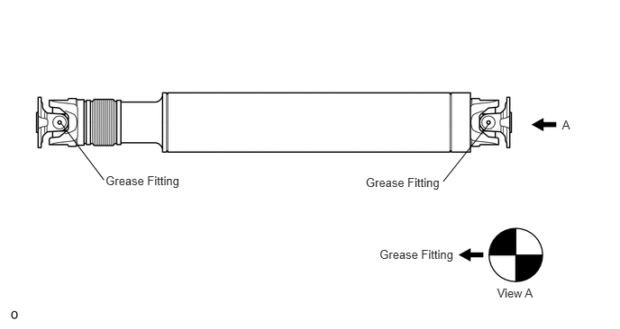
04371H
3.INSPECT UNIVERSAL JOINT SPIDER BEARING