SUSPENSION CONTROL AIR SUSPENSION SYSTEM C1761 Continuous Electric Current to Height Control Compressor Motor
DESCRIPTION
| DTC Code | Detection Condition | Trouble Area |
|---|---|---|
| C1761*1 | Either condition is met:
·
With the AIR SUS relay activated, the vehicle does not return to the standard vehicle height after 90 seconds have elapsed. ·
Power is supplied to the height control compressor motor for 100 seconds or more within a 280 second period. |
·
Air leakage from the air tube or each valve ·
Clogging in the air tube or each valve ·
AIR SUS relay ·
Leveling solenoid valve (No. 2 height control valve) ·
Gate solenoid valve (No. 2 height control valve) ·
Exhaust solenoid valve (No. 1 height control compressor) ·
Height control sensors ·
Wire harness or connector ·
Height control compressor ·
Suspension control ECU |
- HINT:
-
*1: The compressor motor operates continuously to raise vehicle height and allows electric current flow to the AIR SUS relay for 90 seconds or more under the following conditions:
- ·
Vehicle height control is attempted on a steep slope when the vehicle is overloaded.
·The compressor remains on for an excessive period of time or repeatedly turns on and off because of continuous height control switch operation.
·If the compressor remains on because the vehicle is jacked up, the vehicle height is set at a position lower than normal while the engine is running and then the vehicle height control function raises the vehicle.
Thus DTC C1761 may be output and vehicle height control may be suspended. (This is not electrically abnormal.) In this case, however, the vehicle height operation is resumed approximately 10 minutes after the ignition switch is turned ON after the ECU detects the first error. If the ECU detects another error, it takes 70 minutes until control is resumed.
WIRING DIAGRAM
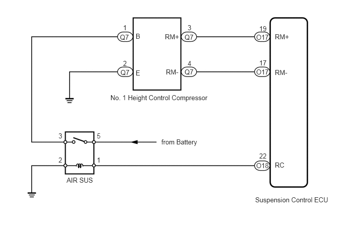
CAUTION / NOTICE / HINT
- NOTICE:
-
After replacing the suspension control ECU, perform registration (See page Suspension>SUSPENSION CONTROL>AIR SUSPENSION SYSTEM>REGISTRATION).
PROCEDURE
Check for air leakage (See page Suspension>SUSPENSION CONTROL>SUSPENSION CONTROL SYSTEM>ADJUSTMENT).
- OK:
No leaks.
OK
NG
Connect the Techstream to the DLC3.
Turn the ignition switch to ON, and turn the Techstream main switch on.
Enter the following menus: Chassis / Air suspension / Active Test.
| Tester Display | Test Part | Control Range | Diagnostic Note |
|---|---|---|---|
| Exhaust Solenoid | Exhaust solenoid valve | ON or OFF | Operation sound of solenoid (clicking sound) can be heard |
- OK:
Operation of solenoid (clicking sound) can be heard
OK
NG
Connect the Techstream to the DLC3.
Turn the ignition switch to ON, and turn the Techstream main switch on.
Enter the following menus: Chassis / Air suspension / Active Test.
| Tester Display | Test Part | Control Range | Diagnostic Note |
|---|---|---|---|
| Rear Gate Solenoid | Gate solenoid valve/ | ON or OFF | Operation sound of solenoid (clicking sound) can be heard |
- OK:
Operation of solenoid (clicking sound) can be heard
OK
NG
Connect the Techstream to the DLC3.
Turn the ignition switch to ON, and turn the Techstream main switch on.
Enter the following menus: Chassis / Air suspension / Active Test.
| Tester Display | Test Part | Control Range | Diagnostic Note |
|---|---|---|---|
| Rear Leveling Solenoid | Leveling solenoid valve | ON or OFF | Operation sound of solenoid (clicking sound) can be heard |
- OK:
Operation of solenoid (clicking sound) can be heard
OK
NG
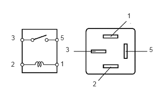
Turn the ignition switch off.
Remove the AIR SUS relay from the engine room relay block.
Measure the resistance according to the value(s) in the table below.
- Standard Resistance:
Tester Connection Condition Specified Condition 3 - 5 When 12 V battery voltage is not applied to terminal 1 and 2 10 kΩ or higher When 12 V battery voltage is applied to terminal 1 and 2 Below 1 Ω
OK
NG
Remove the AIR SUS relay from the engine room relay block.
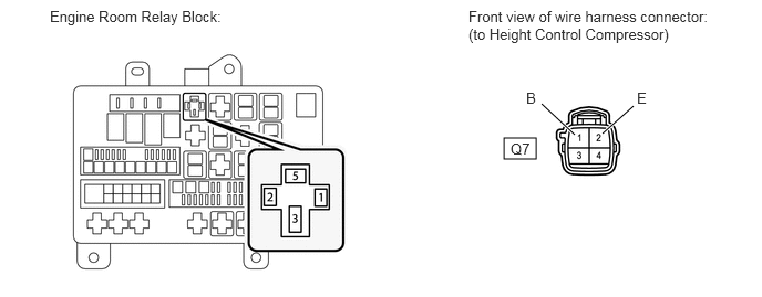
Measure the voltage according to the value(s) in the table below.
- Standard Voltage:
Tester Connection Condition Specified Condition Relay block AIR SUS relay terminal 5 - Body ground Always 11 to 14 V
Disconnect the Q7 compressor connector.
Measure the resistance according to the value(s) in the table below.
- Standard Resistance:
Tester Connection Condition Specified Condition Relay block AIR SUS relay terminal 3 - Q7-1 (B) Always Below 1 Ω Relay block AIR SUS relay terminal 3 or Q7-1 (B) - Body ground Always 10 kΩ or higher Q7-2 (E) - Body ground Always Below 1 Ω
OK
NG
Check the vehicle height (See page Suspension>SUSPENSION CONTROL>SUSPENSION CONTROL SYSTEM>ADJUSTMENT).
OK
NG
Clear the DTC (See page Suspension>SUSPENSION CONTROL>AIR SUSPENSION SYSTEM>DTC CHECK / CLEAR).
Check for DTC (See page Suspension>SUSPENSION CONTROL>AIR SUSPENSION SYSTEM>DTC CHECK / CLEAR).
| Result | Proceed to |
|---|---|
| DTC is output | A |
| DTC is not output | B |
A
B
(See pageGeneral>INTRODUCTION>HOW TO TROUBLESHOOT ECU CONTROLLED SYSTEMS>HOW TO PROCEED WITH TROUBLESHOOTING)