SUSPENSION CONTROL AIR SUSPENSION SYSTEM C1782 Power Source Voltage Malfunction
DESCRIPTION
This circuit provides power to operate the suspension control ECU.
The suspension control ECU, controlling the air suspension system, is activated when the ignition switch is turned ON. The main relay inside the ECU is activated after 2 seconds and the system is operated by +B power source.
| DTC Code | Detection Condition | Trouble Area |
|---|---|---|
| C1782 | Terminal IG or B voltage is 10 V or less, or 16 V or more for 0.5 seconds | ·
Battery ·
Wire harness or connector ·
Suspension control ECU |
WIRING DIAGRAM
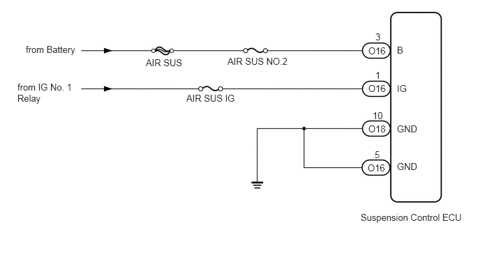
CAUTION / NOTICE / HINT
- NOTICE:
- ·
After replacing the suspension control ECU, perform registration (See page Suspension>SUSPENSION CONTROL>AIR SUSPENSION SYSTEM>REGISTRATION).
·Inspect the fuses for circuits related to this system before performing the following inspection procedure.
PROCEDURE
Connect the Techstream to the DLC3.
Turn the ignition switch to ON, and turn the Techstream main switch on.
Enter the following menus: Chassis / Air suspension / Data List.
| Tester Display | Measurement Item/Range | Normal Condition | Diagnostic Note |
|---|---|---|---|
| +B Power Source Voltage | ECU power supply voltage / min.: 0 V, max.: 25.5 V | Actual battery power supply voltage: 11 to 14 V | - |
| IG Power Source Voltage | ECU power supply voltage / min.: 0 V, max.: 25.5 V | Actual ECU power supply voltage: 11 to 14 V | - |
- Standard voltage:
11 to 14 V
| Result | Proceed to |
|---|---|
| NG | A |
| OK (When troubleshooting according to the Problem Symptoms Table) | B |
| OK (When troubleshooting according to the DTC Chart) | C |
A
B
C
(See pageGeneral>INTRODUCTION>HOW TO TROUBLESHOOT ECU CONTROLLED SYSTEMS>HOW TO PROCEED WITH TROUBLESHOOTING)
Remove the AIR SUS and AIR SUS No. 2 fuses from the engine room relay block.
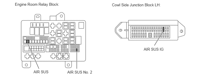
Remove the AIR SUS IG fuse from the cowl side junction block LH.
Measure the resistance of the AIR SUS, AIR SUS No. 2 and AIR SUS IG fuses.
- Standard Resistance:
Fuse Condition Specified Condition AIR SUS Always Below 1 Ω AIR SUS No. 2 Always Below 1 Ω AIR SUS IG Always Below 1 Ω
Reinstall the AIR SUS, AIR SUS No. 2 and AIR SUS IG fuses.
OK
NG
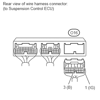
Disconnect the O16 ECU connectors.
Measure the voltage according to the value(s) in the table below.
- Standard Voltage:
Tester Connection Switch Condition Specified Condition O16-3 (B) - Body ground Always 11 to 14 V O16-1 (IG) - Body ground Ignition switch ON 11 to 14 V
OK
NG
Clear the DTC (See page Suspension>SUSPENSION CONTROL>AIR SUSPENSION SYSTEM>DTC CHECK / CLEAR).
Check for DTC (See page Suspension>SUSPENSION CONTROL>AIR SUSPENSION SYSTEM>DTC CHECK / CLEAR).
| Result | Proceed to |
|---|---|
| DTC is not output | A |
| DTC is output | B |
A
B