Home › Brake › BRAKE CONTROL / DYNAMIC CONTROL SYSTEMS › VEHICLE STABILITY CONTROL SYSTEM
RM27L0U _54 Brake _049321 BRAKE CONTROL / DYNAMIC CONTROL SYSTEMS _0235735 VEHICLE STABILITY CONTROL SYSTEM C

BRAKE CONTROL / DYNAMIC CONTROL SYSTEMS  VEHICLE STABILITY CONTROL SYSTEM  C1207/37  Malfunction in Park / Neutral Position Switch  


DESCRIPTION

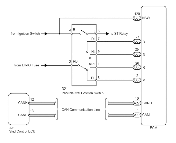
The park/neutral position switch signal is sent to the skid control ECU via the CAN communication system.

When there is a malfunction in the CAN communication system, it will be detected by the diagnostic function.

DTC Code DTC Detection Condition Trouble Area
C1207/37 When all conditions below are met:
·

Yaw rate sensor is normal.

·

G sensor lateral operation is normal.

·

Vehicle speed is 40 km/h (24.9 mph) or more.

·

Reversing signal is output from ECM for 1 second or more.


·

Park/Neutral position switch

·

Harness or connector

·

CAN communication system

·

VSC actuator (skid control ECU)

·

ECM


WIRING DIAGRAM

C179938E07
6.104,5.125 6.563,5.354 0.458,0.229 10 false ECM 0.385,5.135 0.844,5.354 0.458,0.219 10 false A19 0.375,5.271 1.51,5.5 1.135,0.229 10 false Skid Control ECU 2.51,4.385 4.188,4.615 1.677,0.229 10 false CAN Communication Line 2.51,3.531 2.854,3.76 0.344,0.229 10 false D21 5.469,0.667 5.813,0.896 0.344,0.229 10 false D56 5.469,1.604 5.813,1.833 0.344,0.229 10 false D56 5.469,2.135 5.813,2.365 0.344,0.229 10 false D56 5.469,2.656 5.813,2.885 0.344,0.229 10 false D56 5.469,3.188 5.813,3.417 0.344,0.229 10 false D56 5.448,4.125 5.792,4.354 0.344,0.229 10 false A27 5.458,4.604 5.802,4.833 0.344,0.229 10 false A27 5.792,4.594 6.26,4.823 0.469,0.229 10 false CANL 5.802,3.198 6.271,3.427 0.469,0.229 10 false P 5.802,2.667 6.271,2.896 0.469,0.229 10 false R 5.813,2.135 6.281,2.365 0.469,0.229 10 false N 5.802,1.625 6.271,1.854 0.469,0.229 10 false D 5.792,0.646 6.26,0.875 0.469,0.229 10 false NSW 4.5,1.281 5.458,1.51 0.958,0.229 10 false to ST Relay 3.979,1.177 4.146,1.354 0.167,0.177 10 false 5 2.813,1.146 2.979,1.323 0.167,0.177 10 false 4 2.813,2.427 2.979,2.604 0.167,0.177 10 false 2 1.229,3.969 1.417,4.146 0.188,0.177 10 false 12 1.219,4.438 1.396,4.615 0.177,0.177 10 false 13 0.438,1.281 1.698,1.458 1.26,0.177 10 false from Ignition Switch 3.979,1.5 4.146,1.677 0.167,0.177 10 false 7 3.979,2.021 4.146,2.198 0.167,0.177 10 false 9 3.979,2.521 4.146,2.698 0.167,0.177 10 false 1 3.979,3.083 4.146,3.26 0.167,0.177 10 false 6 3.708,3.094 3.906,3.271 0.198,0.177 10 false PL 3.719,2.531 3.917,2.708 0.198,0.177 10 false RL 3.719,2.021 3.917,2.198 0.198,0.177 10 false NL 3.719,1.5 3.917,1.677 0.198,0.177 10 false DL 3.813,1.188 3.938,1.365 0.125,0.177 10 false L 2.969,1.125 3.094,1.302 0.125,0.177 10 false B 2.969,2.417 3.229,2.594 0.26,0.177 10 false RB 5.802,4.115 6.271,4.344 0.469,0.229 10 false CANH 5.5,4.427 5.719,4.604 0.219,0.177 10 false 11 5.5,3.927 5.719,4.104 0.219,0.177 10 false 10 5.51,2.5 5.729,2.677 0.219,0.177 10 false 26 5.5,1.927 5.719,2.104 0.219,0.177 10 false 25 5.521,1.427 5.74,1.604 0.219,0.177 10 false 27 5.469,0.479 5.76,0.656 0.292,0.177 10 false 120 5.552,3 5.677,3.177 0.125,0.177 10 false 2 0.74,4.604 1.208,4.833 0.469,0.229 10 false CANL 0.74,4.104 1.208,4.333 0.469,0.229 10 false CANH 2.51,3.708 4.375,3.938 1.865,0.229 10 false Park/Neutral Position Switch 0.583,2.573 1.667,2.75 1.083,0.177 10 false from LH-IG Fuse

CAUTION / NOTICE / HINT

NOTICE:

When replacing the VSC actuator assembly, perform zero point calibration (See page Brake>BRAKE CONTROL / DYNAMIC CONTROL SYSTEMS>VEHICLE STABILITY CONTROL SYSTEM>CALIBRATION).


PROCEDURE

1.CHECK CAN COMMUNICATION SYSTEM
a.

Check if the CAN communication system DTC is output (See page Power Source / Network>NETWORKING>CAN COMMUNICATION SYSTEM>DIAGNOSIS SYSTEM).

Result
Result Proceed to
DTC is not output A
DTC is output B


A

2.INSPECT PARK / NEUTRAL POSITION SWITCH ASSEMBLY

B

2.INSPECT PARK / NEUTRAL POSITION SWITCH ASSEMBLY
a.
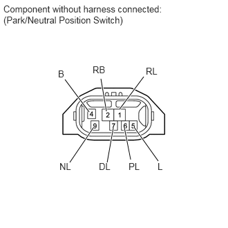
C160109E35
2.385,2.427 2.021,1.917 true 1.615,2.448 1.708,1.927 true 1.969,2.406 1.875,1.927 true 1.604,1.677 1.521,1.188 true 1.052,2.448 1.406,1.927 true 1.802,1.646 2.167,1.156 true 1.344,1.688 0.979,1.198 true 0.052,0.052 2.552,0.5 2.5,0.448 10 false Component without harness connected: (Park/Neutral Position Switch) 1.396,0.969 1.604,1.146 0.208,0.177 10 false RB 0.875,1.031 1.021,1.208 0.146,0.177 10 false B 1.938,2.427 2.146,2.604 0.208,0.177 10 false PL 2.375,2.427 2.583,2.604 0.208,0.177 10 false L 1.49,2.427 1.698,2.604 0.208,0.177 10 false DL 0.896,2.427 1.104,2.604 0.208,0.177 10 false NL 2.198,0.99 2.406,1.167 0.208,0.177 10 false RL

Disconnect the D21 switch connector.


b.

Measure the resistance of the park/neutral position switch when the shift lever is moved to each position.

Standard Resistance:
Tester Connection Condition Specified Condition
2 (RB) - 6 (PL) Shift lever in P Below 1 Ω
2 (RB) - 1 (RL) Shift lever in R
2 (RB) - 9 (NL) Shift lever in N
2 (RB) - 7 (DL) Shift lever in D
Shift lever in S, "+" and "-"
4 (B) - 5 (L) Shift lever in P or N
2 (RB) - 6 (PL) Shift lever not in P 10 kΩ or higher
2 (RB) - 1 (RL) Shift lever not in R
2 (RB) - 9 (NL) Shift lever not in N
2 (RB) - 7 (DL) Shift lever not in D
Shift lever not in S, "+" and "-"
4 (B) - 5 (L) Shift lever not in P and N


OK

3.CHECK PARK / NEUTRAL POSITION SWITCH ASSEMBLY (POWER SOURCE)

NG

REPLACE PARK / NEUTRAL POSITION SWITCH ASSEMBLY

3.CHECK PARK / NEUTRAL POSITION SWITCH ASSEMBLY (POWER SOURCE)
a.
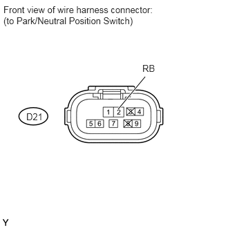
U153453E02
1.781,1.646 2.188,1.156 true 2.146,0.948 2.354,1.125 0.208,0.177 10 false RB 0.052,0.063 2.458,0.51 2.406,0.448 10 false Front view of wire harness connector: (to Park/Neutral Position Switch) 0.396,1.677 0.771,1.906 0.375,0.229 10 false D21

Disconnect the D21 switch connector.


b.

Turn the ignition switch to ON.


c.

Measure the voltage according to the value(s) in the table below.

Standard Voltage:
Tester Connection Switch Condition Specified Condition
D21-2 (RB) - Body ground Ignition switch ON 11 to 14 V
D21-2 (RB) - Body ground Ignition switch off Below 1 V


OK

4.CHECK HARNESS AND CONNECTOR (PARK / NEUTRAL POSITION SWITCH - ECM)

NG

REPAIR OR REPLACE HARNESS OR CONNECTOR (PARK / NEUTRAL POSITION SWITCH - BATTERY)

4.CHECK HARNESS AND CONNECTOR (PARK / NEUTRAL POSITION SWITCH - ECM)
a.
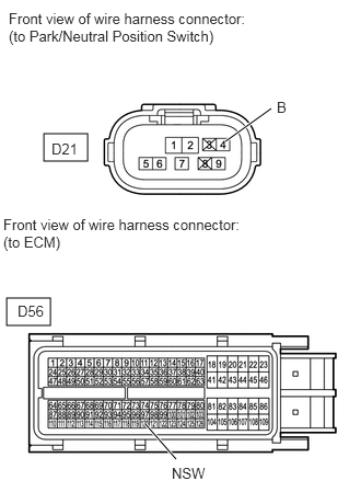
C353357E01
0.417,1.271 0.833,1.531 0.417,0.26 0.063,2.833 0.479,3.094 0.417,0.26 2.146,1.344 2.583,1.031 true 1.385,4.031 1.677,4.365 true 0.083,0.094 2.385,0.448 2.302,0.354 10 false Front view of wire harness connector: (to Park/Neutral Position Switch) 2.635,0.938 2.969,1.188 0.333,0.25 10 false B 0.49,1.333 0.823,1.583 0.333,0.25 10 false D21 1.635,4.417 2.125,4.615 0.49,0.198 10 false NSW 0.031,2.052 2.333,2.406 2.302,0.354 10 false Front view of wire harness connector: (to ECM) 0.167,2.875 0.5,3.125 0.333,0.25 10 false D56

Disconnect the D21 switch connector.


b.

Disconnect the D56 ECM connector.


c.

Measure the resistance according to the value(s) in the table below.

Standard Resistance:
Tester Connection Condition Specified Condition
D21-4 (B) - D56-120 (NSW) Always Below 1 Ω
D21-4 (B) or D56-120 (NSW) - Body ground Always 10 kΩ or higher


OK

5.CHECK HARNESS AND CONNECTOR (PARK / NEUTRAL POSITION SWITCH - ECM)

NG

REPAIR OR REPLACE HARNESS OR CONNECTOR (PARK / NEUTRAL POSITION SWITCH - ECM)

5.CHECK HARNESS AND CONNECTOR (PARK / NEUTRAL POSITION SWITCH - ECM)
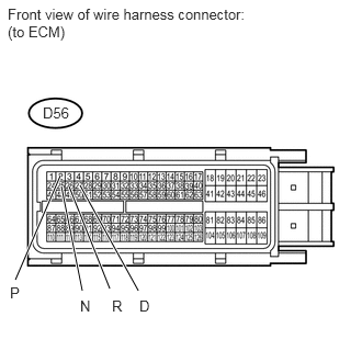
a.
U153538E02
0.76,1.76 1.313,2.76 true 0.656,1.771 1.042,2.74 true 0.583,1.771 0.781,2.76 true 0.573,1.667 0.146,2.656 true 0.073,0.052 2.323,0.385 2.25,0.333 10 false Front view of wire harness connector: (to ECM) 0.406,0.99 0.698,1.167 0.292,0.177 10 false D56 0.094,2.698 0.229,2.865 0.135,0.167 10 false P 0.76,2.823 0.896,2.99 0.135,0.167 10 false N 1.063,2.823 1.198,2.99 0.135,0.167 10 false R 1.323,2.823 1.458,2.99 0.135,0.167 10 false D

Disconnect the D56 ECM connector.


b.

Turn the ignition switch to ON.


c.

Measure the voltage according to the value(s) in the table below.

Standard Voltage:
Tester Connection Switch Condition Specified Condition
D56-2 (P) - Body ground Ignition switch ON
Shift lever in P
11 to 14 V
D56-26 (R) - Body ground Ignition switch ON
Shift lever in R
11 to 14 V*
D56-25 (N) - Body ground Ignition switch ON
Shift lever in N
11 to 14 V
D56-27 (D) - Body ground Ignition switch ON
Shift lever in D
D56-2 (P) - Body ground Ignition switch ON
Shift lever not in P
Below 1 V
D56-26 (R) - Body ground Ignition switch ON
Shift lever not in R
D56-25 (N) - Body ground Ignition switch ON
Shift lever not in N
D56-27 (D) - Body ground Ignition switch ON
Shift lever not in D


HINT:

*: The voltage will drop slightly due to the turning on of the back up light.


Result
Result Proceed to
NG A
OK (for 3UR-FE) B
OK (for 3UR-FBE) C


A

REPAIR OR REPLACE HARNESS OR CONNECTOR (PARK / NEUTRAL POSITION SWITCH - ECM)

B

C