BRAKE CONTROL / DYNAMIC CONTROL SYSTEMS BRAKE ACTUATOR INSTALLATION
CAUTION / NOTICE / HINT
- NOTICE:
-
In case of replacing the skid control ECU, perform the zero point calibration of the steering angle sensor, master cylinder pressure sensor, and yaw rate and deceleration sensor (See page Brake>BRAKE CONTROL / DYNAMIC CONTROL SYSTEMS>VEHICLE STABILITY CONTROL SYSTEM>CALIBRATION).
PROCEDURE

 44540
1.INSTALL VSC ACTUATOR WITH ACTUATOR BRACKET ASSEMBLY
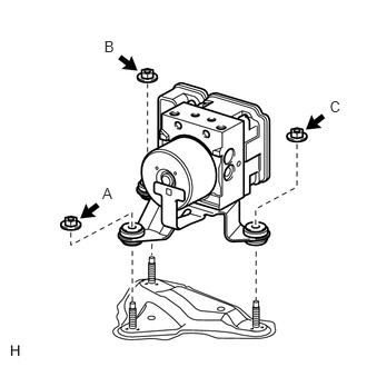
Install the VSC actuator with actuator bracket with the 3 nuts.
- NOTICE:
-
Do not drop the actuator. If dropped, replace it.
Tighten the 3 nuts uniformly in alphabetical order.
- Torque:
- 22 N*m (224 kgf*cm, 16 ft.*lbf)
- NOTICE:
-
Do not damage the brake lines or wire harness.
47312
2.CONNECT BRAKE TUBE
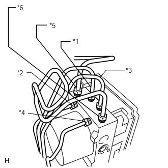
Set each brake line to the correct position on the brake actuator as shown in the illustration.
- HINT:
- ·
*1: FR RH
·*2: FR LH
·*3: RR RH
·*4: RR LH
·*5: FR Master Cylinder
·*6: RR Master Cylinder
Install a new clamp onto the VSC actuator bracket.
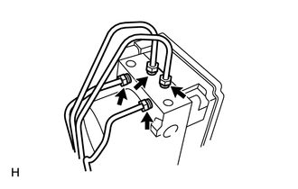
Using a union nut wrench, connect the 4 brake tubes.
- Torque:
- 15 N*m (155 kgf*cm, 11 ft.*lbf)
- NOTICE:
-
Use the formula to calculate special torque values for situations where a union nut wrench is combined with a torque wrench (See page General>INTRODUCTION>REPAIR INSTRUCTION>PRECAUTION).
47311
3.INSTALL BRAKE TUBE
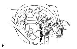
Using a union nut wrench, connect the 2 brake tubes to the brake master cylinder.
- Torque:
- 20 N*m (199 kgf*cm, 14 ft.*lbf)
- NOTICE:
-
Use the formula to calculate special torque values for situations where a union nut wrench is combined with a torque wrench (See page General>INTRODUCTION>REPAIR INSTRUCTION>PRECAUTION).
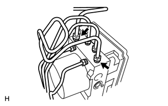
Using a union nut wrench, connect the 2 brake tubes to the VSC actuator.
- Torque:
- 20 N*m (199 kgf*cm, 14 ft.*lbf)
- NOTICE:
-
Use the formula to calculate special torque values for situations where a union nut wrench is combined with a torque wrench (See page General>INTRODUCTION>REPAIR INSTRUCTION>PRECAUTION).
4.CONNECT VSC ACTUATOR CONNECTOR
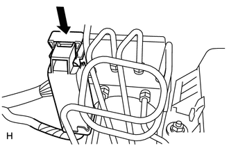
Connect the VSC actuator connector.
5. BLEED BRAKE SYSTEM