RM27L0U
_54
Brake
_049321
BRAKE CONTROL / DYNAMIC CONTROL SYSTEMS
_0235743
RELAY
G
BRAKE CONTROL / DYNAMIC CONTROL SYSTEMS RELAY ON-VEHICLE INSPECTION
PROCEDURE

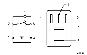
 1.CHECK STOP LIGHT CONTROL RELAY (BRK NO. 1, BRK NO. 2)
a.
Remove the 2 stop light control relays from the engine room relay block.
b.
2.542,1.115 3.01,1.115
false
2.542,1.615 3.01,1.615
false
2.667,0.719 3.01,0.719
false
1.698,0.719 2.01,0.719
false
2.625,0.188 2.531,0.188
2.531,0.188 2.323,0.583
false
0.313,1.396 0.51,1.604
0.198,0.208
10
false
1
1.583,0.635 1.688,0.792
0.104,0.156
10
false
1
1.313,1.396 1.51,1.604
0.198,0.208
10
false
2
3.031,0.625 3.156,0.802
0.125,0.177
10
false
2
0.313,0.844 0.51,1.052
0.198,0.208
10
false
3
3.063,1.531 3.26,1.74
0.198,0.208
10
false
3
0.938,0.365 1.135,0.573
0.198,0.208
10
false
4
2.656,0.104 2.781,0.271
0.125,0.167
10
false
4
1.313,0.844 1.51,1.052
0.198,0.208
10
false
5
3.063,1.021 3.26,1.229
0.198,0.208
10
false
5
Measure the resistance according to the value(s) in the table below.
- Standard Resistance:
for BRK NO. 1 Tester Connection Condition Specified Condition 3 - 4 Battery voltage applied to terminals 1 and 2 10 kΩ or higher Battery voltage not applied to terminals 1 and 2 Below 1 Ω 3 - 5 Battery voltage not applied to terminals 1 and 2 10 kΩ or higher Battery voltage applied to terminals 1 and 2 Below 1 Ω
for BRK NO. 2 Tester Connection Condition Specified Condition 3 - 4 Battery voltage applied to terminals 1 and 2 10 kΩ or higher Battery voltage not applied to terminals 1 and 2 Below 1 Ω
If the result is not as specified, replace the relay.
c.
Install the 2 stop light control relays.