STEERING COLUMN STEERING COLUMN ASSEMBLY(for Manual Tilt and Manual Telescopic Steering Column) DISASSEMBLY
CAUTION / NOTICE / HINT
- NOTICE:
-
When using a vise, do not overtighten it.
PROCEDURE

 89783
1.REMOVE TRANSPONDER KEY COIL
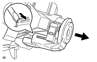
Using a screwdriver, widen the claws attached to the upper bracket by approximately 1.0 mm (0.0394 in.).
Pull out the transponder key coil with the claws open.
- NOTICE:
-
Using excessive force may damage the case.
45271
2.REMOVE UPPER STEERING COLUMN WITH SWITCH BRACKET ASSEMBLY
Secure the steering column in a vise.
Using a center punch, mark the center of the 2 tapered-head bolts.
Using a 3 to 4 mm (0.119 to 0.159 in.) drill, drill a hole in the 2 tapered-head bolts.
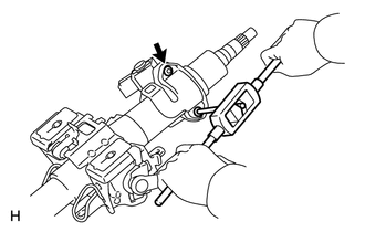
Using a screw extractor, remove the 2 tapered-head bolts, and then remove the upper steering column with switch bracket and the steering lock bracket from the steering column.
69057A
3.REMOVE IGNITION SWITCH LOCK CYLINDER ASSEMBLY
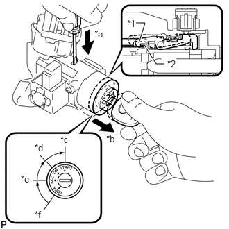
Turn the ignition switch lock cylinder to the ACC position.
| *1 | Claw |
| *2 | Stopper |
| *a | Push |
| *b | Pull |
| *c | START |
| *d | ON |
| *e | ACC |
| *f | LOCK |
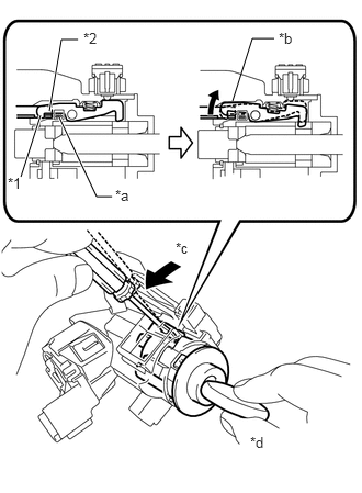
Insert screwdriver in the steering column bracket assembly upper as shown in the illustration. Then slide ignition switch lock cylinder assembly until the claw of the ignition switch lock cylinder assembly comes into contact with the steering column bracket assembly upper stopper.
- HINT:
-
When the ignition lock cylinder assembly disengages, a click sound is heard.
| *1 | Claw |
| *2 | Stopper |
| *a | Drive insertion Hole |
| *b | Claw disengaged |
| *c | Tilt |
| *d | Pull Out |
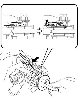
Insert a screwdriver into the hole of the steering column upper with switch bracket assembly. Push the screwdriver downward as shown in the illustration to disengage the claw of the ignition switch lock cylinder assembly. Pull out the ignition switch lock cylinder assembly.
- HINT:
-
When the ignition lock cylinder assembly disengages, a click sound is heard.
84052
4.REMOVE UNLOCK WARNING SWITCH ASSEMBLY
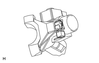
Detach the 2 claws and remove the switch.
85432
5.REMOVE KEY INTERLOCK SOLENOID
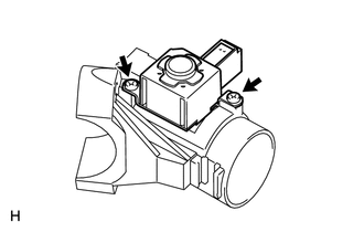
Remove the 2 screws and key interlock solenoid from the switch bracket.
84450
6.REMOVE IGNITION SWITCH ASSEMBLY
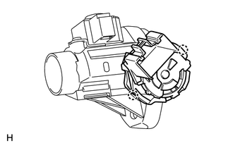
Detach the 2 claws and remove the ignition switch from the switch bracket.
45877A
7.REMOVE STEERING COLUMN BRACKET SPACER
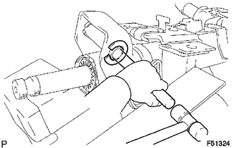
Using a brass bar, hammer and vise, gently strike the central part of the steering column bracket spacer and remove it.
Remove the No. 1 tilt steering support collar from the lower steering column tube.