RM27L0U
_56
Audio / Visual / Telematics
_049331
PARK ASSIST / MONITORING
_0235786
INTUITIVE PARKING ASSIST SYSTEM
U
PARK ASSIST / MONITORING INTUITIVE PARKING ASSIST SYSTEM TERMINALS OF ECU
CHECK CLEARANCE WARNING ECU ASSEMBLY
3.427,0.26 3.833,0.438
0.406,0.177
10
false
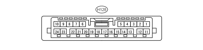
H128
a.
Disconnect the H128 clearance warning ECU assembly connector.
b.
Measure the resistance and voltage according to the value(s) in the table below.
| Terminal No. (Symbol) | Wiring Color | Terminal Description | Condition | Specified Condition |
|---|---|---|---|---|
| H128-11 (IG) - H128-16 (E) | BE - W-B | Power source (IG) | Ignition switch ON, clearance sonar main switch OFF | Below 1 V |
| Ignition switch ON, clearance sonar main switch ON | 11 to 14 V | |||
| H128-16 (E) - Body ground | W-B - Body ground | ECU ground | Always | Below 1 Ω |
c.
Reconnect the H128 clearance warning ECU assembly connector.
d.
Measure the resistance and voltage according to the value(s) in the table below.
| Terminal No. (Symbol) | Wiring Color | Terminal Description | Condition | Specified Condition |
|---|---|---|---|---|
| H128-2 (ER) - H128-16 (E) | Y - W-B | Clearance warning buzzer | Ignition switch ON, clearance sonar main switch ON, shift lever in R and sensor is detecting state (buzzer sounding) | Pulse generation (See waveform 1) |
| Buzzer not sounding | 11 to 14 V | |||
| H128-3 (BOF) - H128-16 (E) | V - W-B | Ultrasonic sensor power source | Ignition switch ON, clearance sonar main switch ON | 7.2 to 8.8 V |
| H128-5 (SOF) - H128-4 (E5) | GR - G | Front sensor communication signal | Ignition switch ON, clearance sonar main switch ON, shift lever except R | Pulse generation (See waveform 3) |
| H128-4 (E5) - H128-16 (E) | G - W-B | ECU ground | Always | Below 1 Ω |
| H128-6 (PL) - H128-16 (E) | P - W-B | Parking position signal | Ignition switch ON, shift lever not in P position | Below 1.5 V |
| Ignition switch ON, shift lever in P position | 7 V or higher | |||
| H128-7 (L1) - H128-16 (E) | G - W-B | Rear corner ultrasonic sensor RH | Clearance warning indicator LED for rear corner sensor RH illuminates | Below 3 V |
| H128-8 (L2) - H128-16 (E) | GR - W-B | Rear corner ultrasonic sensor LH | Clearance warning indicator LED for rear corner sensor LH illuminates | Below 3 V |
| H128-9 (L4) - H128-16 (E) | V - W-B | Front corner ultrasonic sensor RH | Clearance warning indicator LED for front corner sensor RH illuminates | Below 3 V |
| H128-10 (L10) - H128-16 (E) | R - W-B | Clearance warning ECU signal | Clearance warning indicator's operation indicator illuminates | Below 3 V |
| H128-12 (BOR) - H128-16 (E) | R - W-B | Ultrasonic sensor power source | Ignition switch ON, clearance sonar main switch ON | 7.2 to 8.8 V |
| H128-13 (E1) - H128-16 (E) | P - W-B | ECU ground | Always | Below 1 Ω |
| H128-14 (SOR) - H128-13 (E1) | LG - P | Rear sensor communication signal | Ignition switch ON, clearance sonar main switch ON, shift lever in R | Pulse generation (See waveform 2) |
| H128-17 (SPD) - H128-16 (E) | V - W-B | Vehicle speed signal | Ignition switch ON, drive wheels are turned slowly | Alternating between 1.5 to 4.5 V |
| H128-20 (TL) - H128-16 (E) | L - W-B | Illumination light | Ignition switch ON and light control switch except TAIL | Below 1.5 V |
| Ignition switch ON and light control switch TAIL | 7 V or higher | |||
| H128-21 (RL) - H128-16 (E) | LG - W-B | Reverse position signal | Ignition switch ON, shift lever not in R | Below 1.5 V |
| Ignition switch ON, shift lever in R | 7 V or higher | |||
| H128-23 (L3) - H128-16 (E) | BE - W-B | Rear center ultrasonic sensor | Clearance warning indicator LED for rear center sensor illuminates | Below 3 V |
| H128-24 (L5) - H128-16 (E) | LG - W-B | Front corner ultrasonic sensor LH | Clearance warning indicator LED for front corner sensor LH illuminates | Below 3 V |
e.
0.083,1.688 0.531,1.938
0.448,0.25
10
false
GND
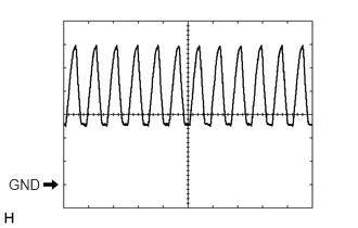
Using an oscilloscope, check waveform 1.
| Item | Content |
|---|---|
| Terminal No. (Symbol) | H128-2 (ER) - H128-16 (E) |
| Tool Setting | 2 V/DIV., 500 μsec./DIV. |
| Condition | Ignition switch ON, clearance sonar main switch ON, shift lever in R and sensor is detecting state (buzzer sounding) |
f.
0.177,0.938 0.531,1.083
0.354,0.146
10
false
GND
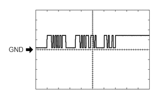
Using an oscilloscope, check waveform 2.
| Item | Content |
|---|---|
| Terminal No. (Symbol) | H128-14 (SOR) - H128-13 (E1) |
| Tool Setting | 5 V/DIV., 1 msec./DIV. |
| Condition | Ignition switch ON, clearance sonar main switch ON, shift lever in R |
g.
0.177,0.938 0.531,1.083
0.354,0.146
10
false
GND
Using an oscilloscope, check waveform 3.
| Item | Content |
|---|---|
| Terminal No. (Symbol) | H128-5 (SOF) - H128-4 (E5) |
| Tool Setting | 5 V/DIV., 1 msec./DIV. |
| Condition | Ignition switch ON, clearance sonar main switch ON, shift lever except R |