RM27L0U
_56
Audio / Visual / Telematics
_049331
PARK ASSIST / MONITORING
_0235791
CLEARANCE SONAR MAIN SWITCH
G
PARK ASSIST / MONITORING CLEARANCE SONAR MAIN SWITCH INSPECTION
PROCEDURE

 84977
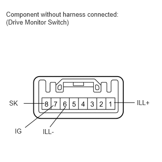
1.INSPECT DRIVE MONITOR SWITCH
a.
Check the resistance.
i.
0.127,0.217 2.723,0.990
2.596,0.773
10
Component without harness connected: (Drive Monitor Switch)
0.194,2.109 0.419,2.271
0.225,0.163
10
SK
0.942,2.194 0.503,2.194
false
0.314,2.696 0.505,2.852
0.191,0.156
10
IG
0.907,2.713 1.190,2.869
0.283,0.156
10
ILL-
2.904,2.097 3.219,2.253
0.316,0.156
10
ILL+
2.858,2.177 2.42,2.177
false
1.391,2.271 1.059,2.695
false
1.133,2.237 0.532,2.706
false
Measure the resistance according to the value(s) in the table below.
- Standard Resistance:
Tester Connection Switch Condition Specified Condition 7 (IG) - 8 (SK) Sonar switch off 10 kΩ or higher Sonar switch on Below 1 Ω
If the result is not as specified, replace the drive monitor switch.
b.
Inspect the illumination operation.
i.
Connect the positive (+) lead of the battery to terminal 1 (ILL+) and the negative (-) lead to terminal 6 (ILL-), and then check that the illumination illuminates.
- OK:
Illumination illuminates.
If the result is not as specified, replace the drive monitor switch.