RM27L0U
_57
Power Source / Network
_049335
NETWORKING
_0235802
CAN COMMUNICATION SYSTEM
J
NETWORKING CAN COMMUNICATION SYSTEM Combination Meter ECU Communication Stop Mode
DESCRIPTION
| Detection Item | Symptom | Trouble Area |
|---|---|---|
| Combination Meter ECU Communication Stop Mode | Either condition is met:
·
"Combination Meter" is not displayed on the "Bus Check" screen. ·
"Combination Meter ECU Communication Stop Mode" in "DTC Communication Table" applies. |
·
Power source or inside of combination meter assembly ·
Combination meter assembly |
WIRING DIAGRAM
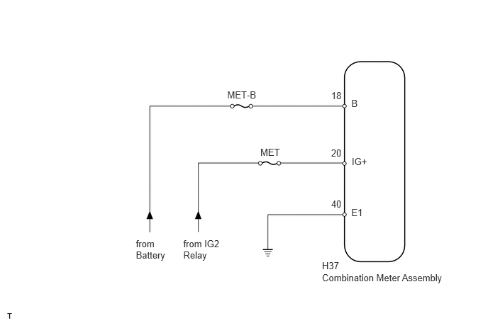
4.729,3.82 5.038,4.032
0.309,0.211
10
H37
5.16,1.437 5.677,1.620
0.517,0.184
10
B
5.16,3.041 5.677,3.225
0.517,0.184
10
E1
4.863,1.328 5.051,1.505
0.188,0.177
10
18
4.863,2.919 5.093,3.096
0.230,0.177
10
40
3.338,1.314 3.789,1.455
0.451,0.141
10
MET-B
1.996,3.503 2.608,3.852
0.613,0.350
10
from Battery
2.692,3.503 3.339,3.879
0.647,0.376
10
from IG2 Relay
5.166,2.287 5.683,2.424
0.517,0.136
10
IG+
4.863,2.169 5.093,2.346
0.230,0.177
10
20
3.823,2.155 4.139,2.298
0.316,0.143
10
MET
4.729,4.002 6.602,4.182
1.873,0.180
10
Combination Meter Assembly
CAUTION / NOTICE / HINT
- NOTICE:
-
Inspect the fuses for circuits related to this system before performing the following inspection procedure.
PROCEDURE
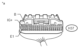
1.CHECK HARNESS AND CONNECTOR (COMBINATION METER ASSEMBLY - BATTERY AND BODY GROUND)
a.
1.108,1.103 0.845,0.597
0.845,0.597 0.728,0.597
false
0.939,1.103 0.73,0.849
0.73,0.849 0.613,0.849
false
0.938,1.232 0.761,1.522
0.761,1.522 0.644,1.522
false
0.425,1.452 0.616,1.594
0.191,0.142
10
E1
0.298,0.763 0.560,0.905
0.262,0.142
10
IG+
0.587,0.517 0.750,0.659
0.163,0.142
10
B
0.08,0.05 0.500,0.192
0.420,0.142
10
*a
2.857,1.106 3.138,1.248
0.281,0.142
10
H37
Disconnect the H37 combination meter assembly connector.
b.
Measure the voltage according to the value(s) in the table below.
- Standard Voltage:
Tester Connection Condition Specified Condition H37-18 (B) - Body ground Always 11 to 14 V H37-20 (IG+) - Body ground Ignition switch ON 11 to 14 V
c.
Measure the resistance according to the value(s) in the table below.
- Standard Resistance:
Tester Connection Condition Specified Condition H37-40 (E1) - Body ground Always Below 1 Ω
| *a | Rear view of wire harness connector
(to Combination Meter Assembly) |
OK
REPLACE COMBINATION METER ASSEMBLY
NG
REPAIR OR REPLACE HARNESS OR CONNECTOR