RM27L0U
_58
Vehicle Interior
_049337
THEFT DETERRENT / KEYLESS ENTRY
_0235816
THEFT DETERRENT SYSTEM
J
THEFT DETERRENT / KEYLESS ENTRY THEFT DETERRENT SYSTEM ECU Power Source Circuit
DESCRIPTION
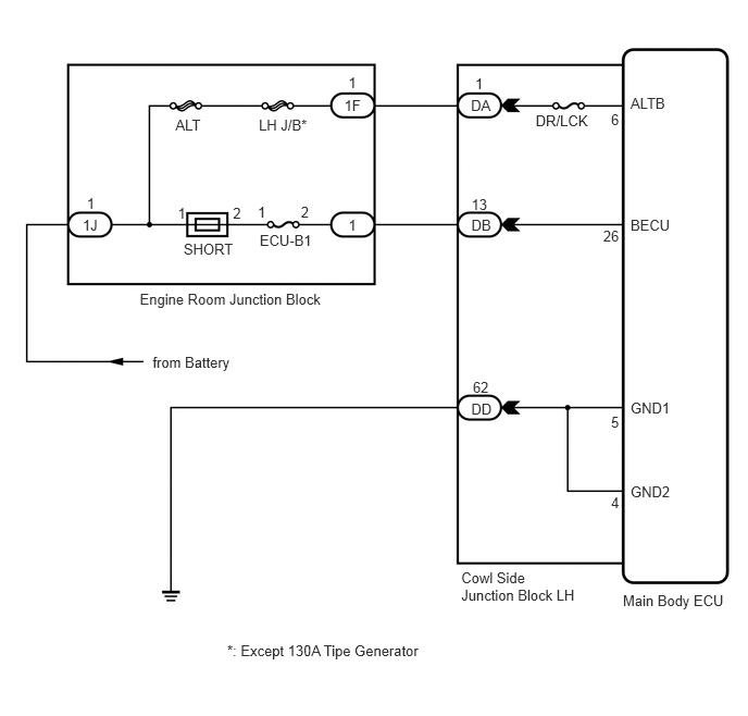
This circuit provides power for main body ECU operation.
WIRING DIAGRAM
3.298,0.929 3.477,1.113
0.179,0.184
10
1F
4.552,0.722 4.731,0.906
0.179,0.184
10
1
2.469,1.951 2.565,2.106
0.096,0.154
10
1
2.883,1.949 2.979,2.132
0.096,0.184
10
2
3.338,0.709 3.434,0.893
0.096,0.184
10
1
3.338,2.068 3.434,2.252
0.096,0.184
10
1
5.854,1.059 5.950,1.243
0.096,0.184
10
6
5.854,3.955 5.950,4.138
0.096,0.184
10
5
5.854,4.73 5.950,4.914
0.096,0.184
10
4
2.232,1.957 2.328,2.140
0.096,0.184
10
2
1.703,1.957 1.799,2.140
0.096,0.184
10
1
0.831,1.869 0.927,2.053
0.096,0.184
10
1
1.462,3.389 2.655,3.572
1.193,0.184
10
from Battery
0.791,2.074 1.012,2.239
0.221,0.165
10
1J
4.512,0.93 4.820,1.095
0.308,0.165
10
DA
4.516,2.069 4.731,2.234
0.214,0.165
10
DB
4.515,3.835 4.852,4.000
0.338,0.165
10
DD
2.488,2.222 3.246,2.378
0.758,0.156
10
ECU-B1
1.759,2.302 2.276,2.453
0.517,0.151
10
SHORT
5.132,1.078 5.733,1.229
0.601,0.151
10
DR/LCK
2.48,1.112 3.127,1.263
0.648,0.151
10
LH J/B*
1.681,1.112 1.981,1.263
0.300,0.151
10
ALT
1.339,2.778 3.464,2.929
2.125,0.151
10
Engine Room Junction Block
6.041,0.903 6.415,1.065
0.375,0.163
10
ALTB
6.041,2.07 6.472,2.233
0.432,0.163
10
BECU
4.516,1.87 4.699,2.035
0.184,0.165
10
13
5.779,2.174 5.963,2.339
0.184,0.165
10
26
4.53,3.626 4.713,3.791
0.184,0.165
10
62
6.041,3.824 6.465,3.970
0.424,0.147
10
GND1
6.041,4.627 6.465,4.774
0.424,0.147
10
GND2
5.968,5.669 7.034,5.841
1.065,0.171
10
Main Body ECU
4.419,5.448 5.556,5.773
1.137,0.325
10
Cowl Side Junction Block LH
2.177,6.142 4.168,6.285
1.991,0.143
10
*: Except 130A Tipe Generator
PROCEDURE
1.CHECK MAIN BODY ECU (POWER SOURCE)
a.
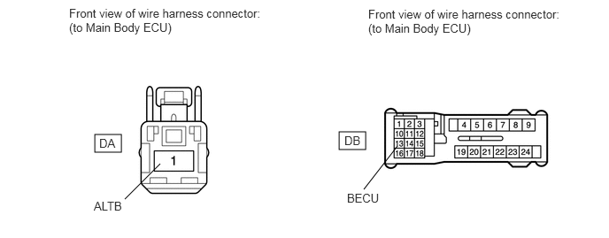
Disconnect the DA and DB main body ECU connectors.
1.115,1.583 1.427,1.792
0.313,0.208
3.99,1.552 4.302,1.76
0.313,0.208
1.469,2.344 1.885,1.927
false
4.281,2.229 4.677,1.719
false
0.813,0.073 3.198,0.49
2.385,0.417
10
false
Front view of wire harness connector: (to Main Body ECU)
4.333,0.083 6.719,0.5
2.385,0.417
10
false
Front view of wire harness connector: (to Main Body ECU)
1.167,1.604 1.479,1.802
0.313,0.198
10
false
DA
4.052,1.573 4.365,1.771
0.313,0.198
10
false
DB
1.104,2.344 1.49,2.51
0.385,0.167
10
false
ALTB
4.083,2.25 4.469,2.417
0.385,0.167
10
false
BECU
b.
Measure the voltage according to the value(s) in the table below.
- Standard Voltage:
Tester Connection Condition Specified Condition DA-1 - Body ground Always 11 to 14 V DB-13 - Body ground Always 11 to 14 V
OK
2.CHECK HARNESS AND CONNECTOR (MAIN BODY ECU - BODY GROUND)
NG
REPAIR OR REPLACE HARNESS OR CONNECTOR
2.CHECK HARNESS AND CONNECTOR (MAIN BODY ECU - BODY GROUND)
a.
0.075,0.033 2.457,0.392
2.383,0.360
10
Front view of wire harness connector: (to Main Body ECU)
1.636,1.285 1.868,1.454
0.232,0.170
10
DD
1.351,2.853 2.461,3.016
1.110,0.163
10
GND1 and GND2
1.097,2.052 1.372,2.849
false
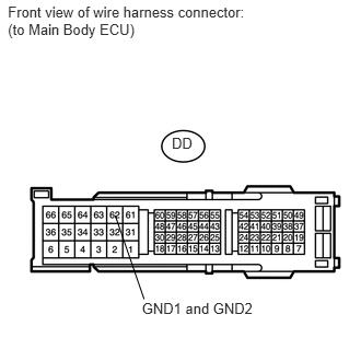
Disconnect the DD main body ECU connector.
b.
Measure the resistance according to the value(s) in the table below.
- Standard Resistance:
Tester Connection Condition Specified Condition DD-62 - Body ground Always Below 1 Ω
OK
PROCEED TO NEXT CIRCUIT INSPECTION SHOWN IN PROBLEM SYMPTOMS TABLE
(See pageVehicle Interior>THEFT DETERRENT / KEYLESS ENTRY>THEFT DETERRENT SYSTEM>PROBLEM SYMPTOMS TABLE)
NG
REPAIR OR REPLACE HARNESS OR CONNECTOR