Home › Vehicle Interior › THEFT DETERRENT / KEYLESS ENTRY › THEFT DETERRENT SYSTEM
RM27L0U _58 Vehicle Interior _049337 THEFT DETERRENT / KEYLESS ENTRY _0235816 THEFT DETERRENT SYSTEM J

THEFT DETERRENT / KEYLESS ENTRY  THEFT DETERRENT SYSTEM  Ignition Switch Circuit  


DESCRIPTION

The main body ECU determines the ignition switch position (off, ACC, ON) based on signals from the IG or ACC circuit.

WIRING DIAGRAM
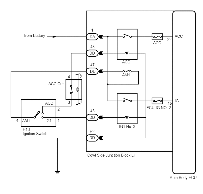
B209245E03
0.854,1.167 1.646,1.344 0.792,0.177 10 false from Battery 3.167,1.208 3.375,1.375 0.208,0.167 10 false DA 3.156,4.781 3.458,4.969 0.302,0.188 10 false DD 3.188,4.563 3.417,4.729 0.229,0.167 10 false 62 3.156,4.063 3.458,4.25 0.302,0.188 10 false DD 3.188,3.833 3.417,4 0.229,0.167 10 false 43 3.177,2.438 3.479,2.625 0.302,0.188 10 false DD 3.188,2.208 3.417,2.375 0.229,0.167 10 false 47 3.156,1.792 3.458,1.979 0.302,0.188 10 false DD 6.167,1.198 6.5,1.365 0.333,0.167 10 false ACC 6.167,3.479 6.5,3.646 0.333,0.167 10 false IG 3.083,5.396 4.99,5.594 1.906,0.198 10 false Cowl Side Junction Block LH 5.979,6.188 7.083,6.354 1.104,0.167 10 false Main Body ECU 5.406,1.427 6.115,1.594 0.708,0.167 10 false ACC 5.167,3.719 6.083,3.885 0.917,0.167 10 false ECU-IG NO. 2 0.802,4.49 1.115,4.656 0.313,0.167 10 false H10 0.802,4.635 1.833,4.802 1.031,0.167 10 false Ignition Switch 2.031,4.167 2.188,4.333 0.156,0.167 10 false 1 0.573,4.167 0.729,4.333 0.156,0.167 10 false 4 2.031,3.771 2.188,3.938 0.156,0.167 10 false 2 3.188,1.563 3.417,1.729 0.229,0.167 10 false 45 3.219,0.979 3.344,1.146 0.125,0.167 10 false 1 5.917,3.563 6.104,3.729 0.188,0.167 10 false 15 5.906,1.313 6.094,1.479 0.188,0.167 10 false 22 2.813,2.625 2.938,2.792 0.125,0.167 10 false 2 2.823,3.51 2.948,3.677 0.125,0.167 10 false 1 2.396,2.625 2.521,2.792 0.125,0.167 10 false 4 2.396,3.531 2.521,3.698 0.125,0.167 10 false 3 4.313,2.104 4.646,2.271 0.333,0.167 10 false ACC 4.313,2.563 4.646,2.729 0.333,0.167 10 false AM1 0.781,4.177 1.115,4.344 0.333,0.167 10 false AM1 1.604,4.177 1.938,4.344 0.333,0.167 10 false IG1 1.594,3.563 1.927,3.729 0.333,0.167 10 false ACC 4.198,4.385 4.917,4.552 0.719,0.167 10 false IG1 No. 3 1.708,2.875 2.365,3.042 0.656,0.167 10 false ACC Cut

PROCEDURE

1.READ VALUE USING TECHSTREAM
a.

Connect a Techstream to the DLC3.


b.

Turn the ignition switch to ON.


c.

Turn the Techstream main switch on.


d.

Select the items below in the Data List and read the display on the Techstream.

Main Body
Item Measurement Item/Range Normal Condition Diagnostic Note
IG SW Ignition switch ON signal ON/OFF ON: Ignition switch is ON
OFF: Ignition switch is off
-
ACC SW Ignition switch ACC signal ON/OFF ON: Ignition switch is ACC
OFF: Ignition switch is off
-

OK:

When the ignition switch is operated, the display changes as shown in the table.


OK

PROCEED TO NEXT CIRCUIT INSPECTION SHOWN IN PROBLEM SYMPTOMS TABLE

NG

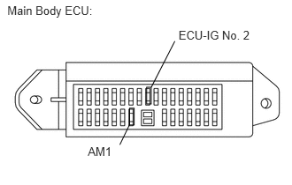
2.INSPECT FUSES (AM1, ECU-IG No. 2)
a.
B188612E04
1.726,1.031 1.779,1.229 0.053,0.198 1.524,1.474 1.41,1.711 false 0.086,0.044 1.204,0.220 1.118,0.176 10 Main Body ECU: 1.034,1.711 1.364,1.864 0.331,0.154 10 AM1 1.526,1.28 1.579,1.478 0.053,0.198 2.058,0.486 1.781,1.03 false 2.102,0.333 3.007,0.486 0.905,0.154 10 ECU-IG No. 2

Remove the AM1 and ECU-IG No. 2 fuses from the main body ECU.


b.

Measure the resistance according to the value(s) in the table below.

Standard Resistance:
Tester Connection Condition Specified Condition
AM1 fuse Always Below 1 Ω
ECU-IG No. 2 fuse Always Below 1 Ω


OK

3.CHECK HARNESS AND CONNECTOR (BATTERY - MAIN BODY ECU)

NG

REPLACE FUSE

3.CHECK HARNESS AND CONNECTOR (BATTERY - MAIN BODY ECU)
a.
U151906E01
0.07,0.051 2.433,0.410 2.363,0.360 10 Front view of wire harness connector: (to Main Body ECU) 0.456,1.892 0.688,2.062 0.232,0.170 10 DA 1.201,2.925 1.423,3.078 0.222,0.152 10 IG 1.378,2.901 1.994,2.406 false

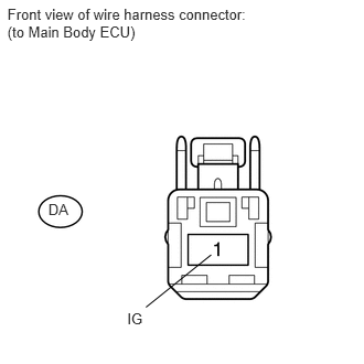
Disconnect the DA main body ECU connector.


b.

Measure the voltage according to the value(s) in the table below.

Standard Voltage:
Tester Connection Condition Specified Condition
DA-1 - Body ground Always 11 to 14 V


OK

4.INSPECT IGNITION SWITCH ASSEMBLY

NG

REPAIR OR REPLACE HARNESS OR CONNECTOR

4.INSPECT IGNITION SWITCH ASSEMBLY
a.
B125076E12
1.302,1.823 0.688,2.094 false 0.073,0.094 2.563,0.448 2.49,0.354 10 false Component without harness connected: (Ignition Switch) 0.719,3.135 1.167,3.323 0.448,0.188 10 false LOCK 1.573,2.771 1.938,2.958 0.365,0.188 10 false ACC 2.302,3.104 2.583,3.271 0.281,0.167 10 false ON 2.542,3.688 3.063,3.865 0.521,0.177 10 false START 0.177,2.042 0.708,2.219 0.531,0.177 12 false No Pin

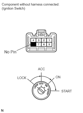
Disconnect the H10 ignition switch connector.


b.

Measure the resistance according to the value(s) in the table below.

Standard Resistance:
Tester Connection Switch Condition Specified Condition
1 - 4 Ignition switch ON Below 1 Ω
2 - 4 Ignition switch ACC Below 1 Ω


OK

5.CHECK HARNESS AND CONNECTOR (MAIN BODY ECU - IGNITION SWITCH AND BODY GROUND)

NG

REPLACE IGNITION SWITCH ASSEMBLY

5.CHECK HARNESS AND CONNECTOR (MAIN BODY ECU - IGNITION SWITCH AND BODY GROUND)
a.
U153188E02
1.292,3.875 0.729,4.323 false 2.802,3.5 2.292,3.823 false 0.063,0.094 2.458,0.479 2.396,0.385 10 false Front view of wire harness connector: (to Main Body ECU) 0.073,2.375 2.458,2.792 2.385,0.417 10 false Front view of wire harness connector: (to Ignition Switch) 1.573,1 1.802,1.167 0.229,0.167 10 false DD 2.844,3.333 3.167,3.51 0.323,0.177 10 false AM1 0.438,4.323 0.719,4.5 0.281,0.177 10 false IG1 0.313,3.708 0.604,3.875 0.292,0.167 10 false H10

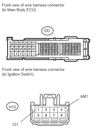
Disconnect the DD main body ECU connector.


b.

Disconnect the H10 ignition switch connector.


c.

Measure the resistance according to the value(s) in the table below.

Standard Resistance:
Tester Connection Condition Specified Condition
DD-47 - H10-4 (AM1) Always Below 1 Ω
DD-43 - H10-1 (IG1) Always Below 1 Ω
DD-45 - H10-2 (ACC) Always Below 1 Ω
DD-62 - Body ground Always Below 1 Ω
DD-47 - Body ground Always 10 kΩ or higher
DD-43 - Body ground Always 10 kΩ or higher
DD-45 - Body ground Always 10 kΩ or higher


OK

REPLACE MAIN BODY ECU

NG

REPAIR OR REPLACE HARNESS OR CONNECTOR