Home › Vehicle Interior › THEFT DETERRENT / KEYLESS ENTRY › THEFT DETERRENT SYSTEM
RM27L0U _58 Vehicle Interior _049337 THEFT DETERRENT / KEYLESS ENTRY _0235816 THEFT DETERRENT SYSTEM J

THEFT DETERRENT / KEYLESS ENTRY  THEFT DETERRENT SYSTEM  Security Horn Circuit  


DESCRIPTION

When the theft deterrent system is operating, the main body ECU outputs a signal continuously at 0.4 second intervals, causing the security horn to sound.


WIRING DIAGRAM
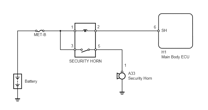
B160795E05
5.563,0.969 5.813,1.146 0.25,0.177 10 false SH 5.563,1.719 5.792,1.906 0.229,0.188 10 false H1 5.563,1.885 6.625,2.052 1.063,0.167 10 false Main Body ECU 4.417,2.458 4.708,2.635 0.292,0.177 10 false A33 4.417,2.625 5.302,2.802 0.885,0.177 10 false Security Horn 2.385,2.031 3.594,2.229 1.208,0.198 10 false SECURITY HORN 0.854,2.729 1.344,2.927 0.49,0.198 10 false Battery 1.167,1.115 1.635,1.313 0.469,0.198 10 false MET-B 5.302,0.854 5.427,1.031 0.125,0.177 10 false 6 4.281,2.177 4.406,2.354 0.125,0.177 10 false 1 2.448,0.854 2.573,1.031 0.125,0.177 10 false 1 3.354,0.844 3.479,1.021 0.125,0.177 10 false 2 3.375,1.51 3.5,1.688 0.125,0.177 10 false 5 2.448,1.5 2.573,1.677 0.125,0.177 10 false 3

PROCEDURE

1.PERFORM ACTIVE TEST USING TECHSTREAM (SECURITY HORN)
a.

Operate the Techstream according to the steps on the display and select Active Test.

Main Body
Tester Display Test Part Control Range Diagnostic Note
Security Horn Security horn ON/OFF -

OK:

Security horn operates normally.


OK

PROCEED TO NEXT CIRCUIT INSPECTION SHOWN IN PROBLEM SYMPTOMS TABLE

NG

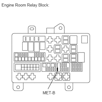
2.INSPECT FUSE (MET-B)
a.
B191994E02
1.927,2.281 1.948,2.385 0.021,0.104 1.948,2.281 1.927,2.313 false 1.948,2.302 1.927,2.333 false 1.948,2.323 1.927,2.354 false 1.948,2.354 1.927,2.375 false 1.948,2.375 1.927,2.396 false 1.938,2.396 1.615,3 false 0.052,0.083 1.76,0.25 1.708,0.167 10 false Engine Room Relay Block: 1.438,3.042 1.99,3.229 0.552,0.188 10 true MET-B

Remove the MET-B fuse from the engine room relay block unit B.


b.

Measure the resistance according to the value(s) in the table below.

Standard Resistance:
Tester Connection Condition Specified Condition
MET-B fuse Always Below 1 Ω


OK

3.INSPECT SECURITY HORN RELAY

NG

REPLACE FUSE

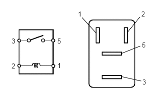
3.INSPECT SECURITY HORN RELAY
B443057E02
1.698,0.365 1.99,0.688 false 2.896,0.354 2.635,0.677 false 2.906,0.958 2.51,1.115 false 2.927,1.688 2.51,1.594 false 0.24,0.771 0.344,0.917 0.104,0.146 10 false 3 0.24,1.292 0.344,1.438 0.104,0.146 10 false 2 1.188,0.771 1.292,0.917 0.104,0.146 10 false 5 1.188,1.281 1.271,1.427 0.083,0.146 10 false 1 1.615,0.208 1.698,0.354 0.083,0.146 10 false 1 2.927,0.208 3.01,0.354 0.083,0.146 10 false 2 2.938,0.854 3.021,1 0.083,0.146 10 false 5 2.948,1.625 3.031,1.771 0.083,0.146 10 false 3

a.

Remove the SECURITY HORN relay from the engine room relay block.

b.

Measure the resistance according to the value(s) in the table below.

Standard Resistance:
Tester Connection Condition Specified Condition
3 - 5 When battery voltage is not applied between terminals 1 and 2 10 kΩ or higher
When battery voltage is applied to terminals 1 and 2 Below 1 Ω


OK

4.INSPECT SECURITY HORN ASSEMBLY

NG

REPLACE SECURITY HORN RELAY

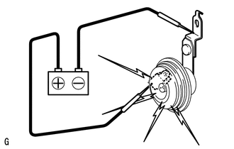
4.INSPECT SECURITY HORN ASSEMBLY

b.

Check operation of the horn.

OK:
Measurement Condition Specified Condition
Battery positive (+) → Terminal 1
Battery negative (-) → Horn bracket
Horn sounds


OK

5.CHECK HARNESS AND CONNECTOR (SECURITY HORN RELAY - BATTERY)

NG

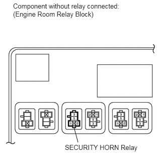
5.CHECK HARNESS AND CONNECTOR (SECURITY HORN RELAY - BATTERY)
a.
B165963E04
1.531,2.635 1.615,2.948 false 0.271,0.042 2.74,0.385 2.469,0.344 10 false Component without relay connected: (Engine Room Relay Block) 1.344,2.969 3.083,3.281 1.74,0.313 10 false SECURITY HORN Relay

Remove the SECURITY HORN relay from the engine room relay block.

b.

Measure the voltage according to the value(s) in the table below.

Standard Voltage:
Tester Connection Condition Specified Condition
Engine room relay block security horn relay terminal 1 - Body ground Always 11 to 14 V
Engine room relay block security horn relay terminal 3 - Body ground Always


OK

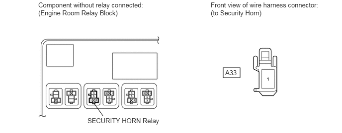
6.CHECK HARNESS AND CONNECTOR (SECURITY HORN RELAY - SECURITY HORN)

NG

REPAIR OR REPLACE HARNESS OR CONNECTOR

6.CHECK HARNESS AND CONNECTOR (SECURITY HORN RELAY - SECURITY HORN)
a.

Remove the SECURITY HORN relay from the engine room relay block.

B443058E03
4.677,1.427 5.031,1.635 0.354,0.208 1.969,2.177 2.156,2.438 false 0.802,0.021 3.156,0.385 2.354,0.365 10 false Component without relay connected: (Engine Room Relay Block) 4.417,0.021 6.771,0.385 2.354,0.365 10 false Front view of wire harness connector: (to Security Horn) 1.833,2.458 3.427,2.656 1.594,0.198 10 false SECURITY HORN Relay 4.719,1.448 5.031,1.625 0.313,0.177 10 false A33


b.

Disconnect the A33 security horn connector.


c.

Measure the resistance according to the value(s) in the table below.

Standard Resistance:
Tester Connection Condition Specified Condition
Engine room relay block security horn relay terminal 5 - A33-1 Always Below 1 Ω


OK

7.CHECK HARNESS AND CONNECTOR (MAIN BODY ECU - SECURITY HORN RELAY)

NG

REPAIR OR REPLACE HARNESS OR CONNECTOR

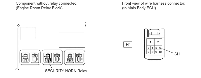
7.CHECK HARNESS AND CONNECTOR (MAIN BODY ECU - SECURITY HORN RELAY)
a.

Remove the SECURITY HORN relay from the engine room relay block.

B443059E02
4.406,1.5 4.708,1.698 0.302,0.198 1.854,2.448 1.708,2.208 false 6.177,1.906 5.76,1.74 false 0.563,0.031 2.823,0.375 2.26,0.344 10 false Component without relay connected: (Engine Room Relay Block) 4.354,0.031 6.615,0.375 2.26,0.344 10 false Front view of wire harness connector: (to Main Body ECU) 1.604,2.458 3.146,2.635 1.542,0.177 10 false SECURITY HORN Relay 6.219,1.854 6.521,2.01 0.302,0.156 10 false SH 4.49,1.521 4.729,1.75 0.24,0.229 10 false H1


b.

Disconnect the H1 main body ECU connector.


c.

Measure the resistance according to the value(s) in the table below.

Standard Resistance:
Tester Connection Condition Specified Condition
Engine room relay block security horn relay terminal 2 - H1-6 (SH) Always Below 1 Ω


OK

REPLACE MAIN BODY ECU

NG

REPAIR OR REPLACE HARNESS OR CONNECTOR