Home › Vehicle Interior › THEFT DETERRENT / KEYLESS ENTRY › THEFT DETERRENT SYSTEM
RM27L0U _58 Vehicle Interior _049337 THEFT DETERRENT / KEYLESS ENTRY _0235816 THEFT DETERRENT SYSTEM J

THEFT DETERRENT / KEYLESS ENTRY  THEFT DETERRENT SYSTEM  Horn Circuit  


DESCRIPTION

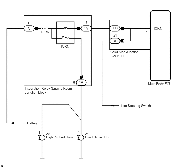
When the theft deterrent system is switched from the armed state to the alarm sounding state, the main body ECU transmits a signal to cause the horn to sound at intervals of 0.4 seconds.

WIRING DIAGRAM
B191886E02
1.073,1.073 1.313,1.24 0.24,0.167 10 false 1C 1.125,0.854 1.25,1.021 0.125,0.167 10 false 1 3.51,0.844 3.698,1.01 0.188,0.167 10 false 7 4.677,0.844 4.865,1.01 0.188,0.167 10 false 1 5.958,1.188 6.146,1.354 0.188,0.167 10 false 25 4.646,1.354 4.885,1.521 0.24,0.167 10 false 21 2.99,3.281 3.115,3.448 0.125,0.167 10 false 8 2.438,1.813 2.885,1.979 0.448,0.167 10 false HORN 1.615,1.219 2.063,1.385 0.448,0.167 10 false HORN 6.24,1.073 6.688,1.24 0.448,0.167 10 false HORN 6.063,3.333 7.115,3.5 1.052,0.167 10 false Main Body ECU 4.927,4.229 6.292,4.396 1.365,0.167 10 false from Steering Switch 4.521,2.031 5.813,2.333 1.292,0.302 10 false Cowl Side Junction Block LH 1.021,3.521 3.063,3.875 2.042,0.354 10 false Integration Relay (Engine Room Junction Block) 1.885,5.375 2.104,5.531 0.219,0.156 10 false A8 1.573,5.313 1.708,5.49 0.135,0.177 10 false 1 3.198,5.313 3.333,5.49 0.135,0.177 10 false 1 1.885,5.51 3.052,5.688 1.167,0.177 10 false High Pitched Horn 3.49,5.375 3.708,5.531 0.219,0.156 10 false A9 3.49,5.51 4.656,5.688 1.167,0.177 10 false Low Pitched Horn 0.802,4.938 1.646,5.115 0.844,0.177 10 false from Battery 3.438,1.073 3.677,1.24 0.24,0.167 10 false 1A 3.24,3.271 3.479,3.438 0.24,0.167 10 false 1A 4.615,1.583 4.896,1.75 0.281,0.167 10 false DD 4.625,1.063 4.865,1.229 0.24,0.167 10 false DB

PROCEDURE

1.INSPECT HORNS
a.

Press the horn switch and check if the horns sound.

Result
Result Proceed to
Horns sound A
Horns do not sound B


A

2.PERFORM ACTIVE TEST USING TECHSTREAM

B

GO TO HORN SYSTEM (PROBLEM SYMPTOMS TABLE)

2.PERFORM ACTIVE TEST USING TECHSTREAM
a.

Connect a Techstream to the DLC3.


b.

Turn the ignition switch to ON.


c.

Turn a Techstream main switch on.


d.

Select the item below in the Active Test and then check that the horns operate.

Main Body
Tester Display Test Part Control Range Diagnostic Note
Vehicle Horn Vehicle horns ON/OFF -

OK:

The vehicle horns sound or stop correctly when operating them through the Techstream.


OK

PROCEED TO NEXT CIRCUIT INSPECTION SHOWN IN PROBLEM SYMPTOMS TABLE

NG

3.CHECK HARNESS AND CONNECTOR (MAIN BODY ECU - ENGINE ROOM JUNCTION BLOCK)
a.

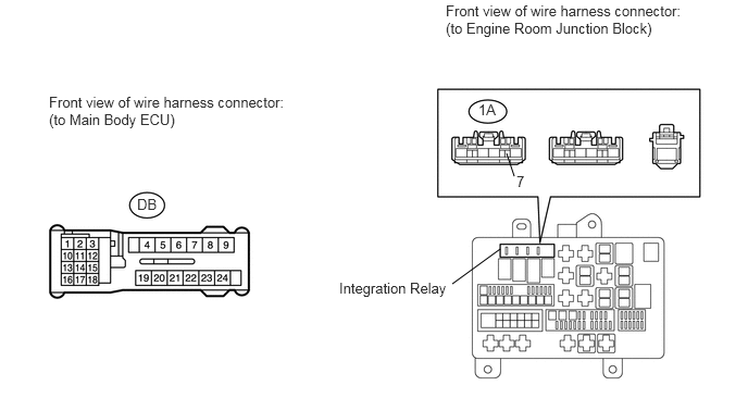
Disconnect the DB main body ECU connector.
U153299E02
4.854,1.469 4.927,1.688 false 4.333,2.719 4.792,2.385 false 0.469,0.896 2.875,1.26 2.406,0.365 10 false Front view of wire harness connector: (to Main Body ECU) 1.313,1.875 1.542,2.042 0.229,0.167 10 false DB 3.25,2.677 4.354,2.854 1.104,0.177 10 false Integration Relay 4.271,0.021 6.646,0.365 2.375,0.344 10 false Front view of wire harness connector: (to Engine Room Junction Block) 4.583,0.969 4.813,1.135 0.229,0.167 10 false 1A 4.948,1.656 5.073,1.802 0.125,0.146 10 false 7


b.

Remove the integration relay from the engine room junction block.


c.

Measure the resistance according to the value(s) in the table below.

Standard Resistance:
Tester Connection Condition Specified Condition
DB-1 - 1A-7 Always Below 1 Ω
DB-1 or 1A-7 - Body ground Always 10 kΩ or higher


OK

REPLACE MAIN BODY ECU

NG

REPAIR OR REPLACE HARNESS OR CONNECTOR