LIGHTING (INT) LIGHTING SYSTEM Illumination Circuit
DESCRIPTION
Upon receiving signals from the switches, the main body ECU illuminates the lights.
WIRING DIAGRAM
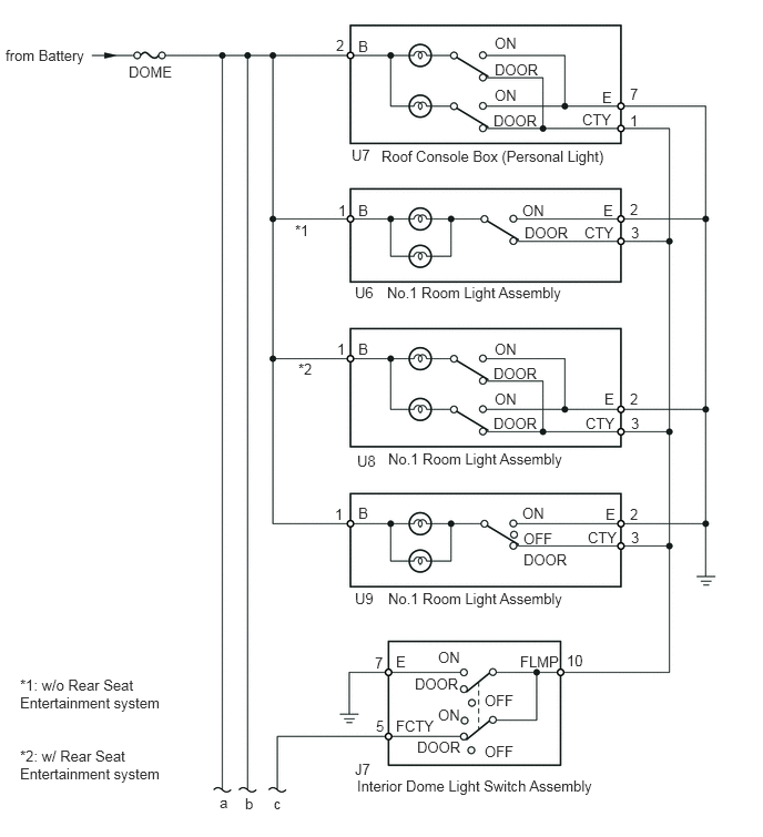
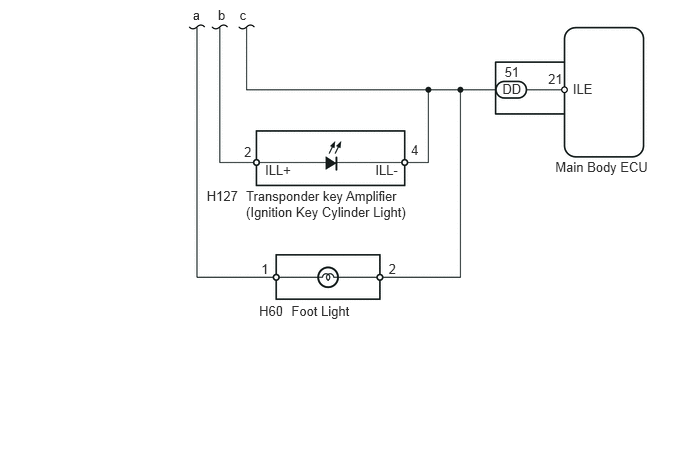
PROCEDURE
Connect the Techstream to DLC3.
Turn the ignition switch to ON.
Turn the Techstream on.
Turn the room light switch to the DOOR position.
All doors closed (courtesy light switches OFF).
Enter the following menus: Body Electrical / Body / Active Test / Illuminated Entry System.
Check the illumination lights while operating the main body ECU using the Techstream.
| Tester Display | Test Part | Control Range | Diagnostic Note |
|---|---|---|---|
| Illuminated Entry System | Illumination light | ON or OFF | - |
- OK:
The illuminated entry system operates normally when operating it through the Techstream.
| Result | Proceed to |
|---|---|
| OK | A |
| NG (All lights do not turn on) | B |
| NG (Only ignition key cylinder light does not turn on) | C |
| NG (Only foot light does not turn on) | D |
| NG (Room lights do not turn on) | E |
A
B
C
D
E
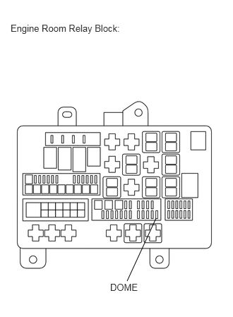
Remove the DOME fuse from the engine room relay block.
Measure the resistance according to the value(s) in the table below.
- Standard Resistance:
Tester Connection Condition Specified Condition DOME fuse Always Below 1 Ω
Reinstall the DOME.
OK
NG
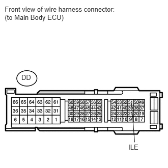
Disconnect the DD main body ECU connector.
measure the voltage according to the value(s) in the table below.
- Standard Voltage:
Tester Connection Condition Specified Condition DD-51 (ILE) - Body ground Always 11 to 14 V
Reconnect the main body ECU connector.
OK
NG
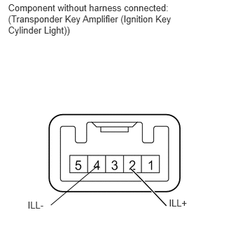
Remove the transponder key amplifier (ignition key cylinder light) (See page Vehicle Interior>THEFT DETERRENT / KEYLESS ENTRY>TRANSPONDER KEY AMPLIFIER>REMOVAL).
Connect the battery positive (+) lead to terminal 2 (ILL+) and the negative (-) lead to terminal 4 (ILL-), and then check that the light turns on.
- OK:
Tester Connection Specified Condition Positive battery → 2 (ILL+)
negative battery → 4 (ILL-)Ignition key cylinder light turns on.
Reinstall the transponder key amplifier (ignition key cylinder light).
OK
NG
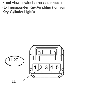
Disconnect the H127 transponder key amplifier (ignition key cylinder light) connector.
Measure the voltage according to the value(s) in the table below.
- Standard Voltage:
Tester Connection Condition Specified Condition H127-2 (ILL+) - Body ground Always 11 to 14 V
Reconnect the transponder key amplifier (ignition key cylinder light) connector.
OK
NG
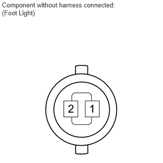
Remove the foot light (See page Vehicle Interior>LIGHTING (INT)>FOOTWELL LIGHT>REMOVAL).
Connect the battery positive (+) lead to terminal 2 and the negative (-) lead to terminal 1, and then check that the light turns on.
- OK:
Tester Connection Specified Condition Positive battery → 1
negative battery → 2Foot light turns on.
Reinstall the foot light.
OK
NG
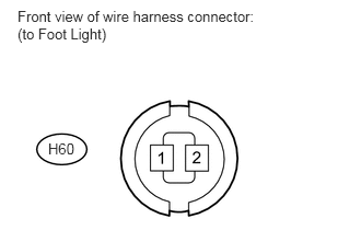
Disconnect the H60 foot light connector.
Measure the voltage according to the value(s) in the table below.
- Standard Voltage:
Tester Connection Condition Specified Condition H60-1 - Body ground Always 11 to 14 V
Reconnect the foot light connector.
OK
NG
Connect the Techstream to DLC3.
Turn the ignition switch to ON.
Turn the Techstream on.
Turn the room light switch DOOR position.
All doors closed (courtesy light switches OFF).
Enter the following menus: Body Electrical / Body / Active Test / Illuminated Entry System.
Check the illumination lights while operating the main body ECU using the Techstream.
| Tester Display | Test Part | Control Range | Diagnostic Note |
|---|---|---|---|
| Illuminated Entry System | Illumination light | ON or OFF | - |
- OK:
The illuminated entry system operates normally when operating it through the Techstream.
| Result | Proceed to |
|---|---|
| NG (All room lights do not turn on) | A |
| NG (Personal light does not turn on) | B |
| NG (No. 1 room light does not turn on) | C |
| NG (No. 2 room light does not turn on) | D |
A
B
C
D
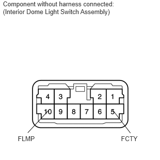
Remove the interior dome light switch assembly (See page Vehicle Interior>LIGHTING (INT)>ROOM LIGHT SWITCH>REMOVAL).
Measure the resistance according to the value(s) in the table below.
- Standard Resistance:
Tester Connection Switch Condition Specified Condition 5 (FCTY) - 10 (FLMP) interior room light switch DOOR Below 1 Ω
Reinstall the interior room light switch assembly.
OK
NG
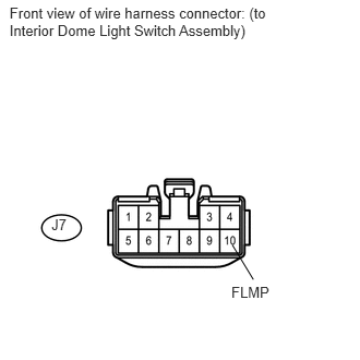
Disconnect the J7 interior dome light switch assembly connector.
Measure the voltage according to the value(s) in the table below.
- Standard Voltage:
Tester Connection Switch Condition Specified Condition J7-10 (FLMP) - Body ground Room light switch DOOR 11 to 14 V
Reconnect the interior room light switch assembly connector.
OK
NG
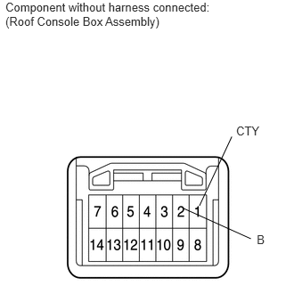
Remove the roof console box assembly.
for short type roof console box (See page Vehicle Interior>INTERIOR PANELS / TRIM>FRONT CONSOLE BOX>DISASSEMBLY).
for long type roof console box (See page Vehicle Interior>INTERIOR PANELS / TRIM>FRONT CONSOLE BOX>DISASSEMBLY).
Roof console box (personal light) switch is DOOR position.
Connect the battery positive (+) lead to terminal 2 (B) and the negative (-) lead to terminal 1 (CTY), and then check that the light turns on.
- OK:
Tester Connection Specified Condition Positive battery → 2 (B)
negative battery → 1 (CTY)Personal light turns on.
Reinstall the roof console box assembly.
| Result | Proceed to |
|---|---|
| OK | A |
| NG (for short type roof console box) | B |
| NG (for long type roof console box) | C |
A
B
C
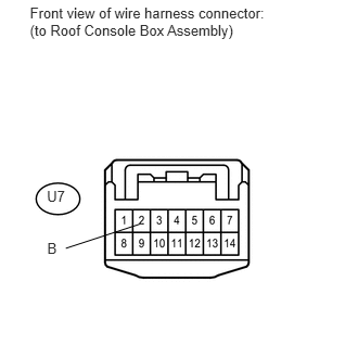
Disconnect the U7 roof console box assembly connector.
Measure the voltage according to the value(s) in the table below.
- Standard Voltage:
Tester Connection Condition Specified Condition U7-2 (B) - Body ground Always 11 to 14 V
Reconnect the roof console box assembly connector.
OK
NG
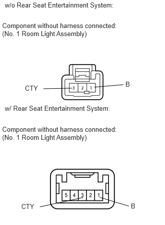
Remove the No. 1 room light assembly.
w/o rear seat entertainment system (See page Vehicle Interior>INTERIOR PANELS / TRIM>ROOF HEADLINING>REMOVAL)
w/ rear seat entertainment system (See page Vehicle Interior>INTERIOR PANELS / TRIM>ROOF HEADLINING>REMOVAL)
No. 1 room light switch is DOOR position.
Connect the battery positive (+) lead to terminal 1(B) and the negative (-) lead to terminal 3 (CTY), and then check that the light turns on.
- OK:
w/o Rear Seat Entertainment System Tester Connection Specified Condition Positive battery → 1 (B)
negative battery → 3 (CTY)No. 1 room light turns on.
w/ Rear Seat Entertainment System Tester Connection Specified Condition Positive battery → 1 (B)
negative battery → 3 (CTY)No. 1 room light turns on.
Reinstall the No. 1 room light assembly.
| Result | Proceed to |
|---|---|
| OK | A |
| NG (w/o Rear seat entertainment system) | B |
| NG (w/ Rear seat entertainment system) | C |
A
B
C
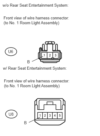
Disconnect the U6*1 or U8*2 No. 1 room light assembly connector.
*1: w/o Rear seat entertainment system
*2: w/ Rear seat entertainment system
Measure the voltage according to the value(s) in the table below.
- Standard Voltage:
w/o Rear Seat Entertainment System Tester Connection Condition Specified Condition U6-1 (B) - Body ground Always 11 to 14 V
w/ Rear Seat Entertainment System Tester Connection Condition Specified Condition U8-1 (B) - Body ground Always 11 to 14 V
Reconnect the No. 1 room light assembly connector.
OK
NG
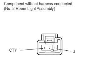
Remove the No. 2 room light assembly (See page Vehicle Interior>INTERIOR PANELS / TRIM>ROOF HEADLINING>REMOVAL).
No. 2 room light switch is OFF position.
Connect the battery positive (+) lead to terminal 1 (B) and the negative (-) lead to terminal 3 (CTY), and then check that the light turns on.
- OK:
Tester Connection Specified Condition Positive battery → 1 (B)
negative battery → 3 (CTY)No. 2 room light turns on.
Reinstall the No. 2 room light assembly.
OK
NG
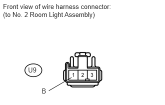
Disconnect the U9 No. 2 room light assembly connector.
Measure the voltage according to the value(s) in the table below.
- Standard Voltage:
Tester Connection Condition Specified Condition U9-1 (B) - Body ground Always 11 to 14 V
Reconnect the No. 2 room light assembly connector.
OK
NG