Home › Vehicle Interior › LIGHTING (INT) › LIGHTING SYSTEM
RM27L0U _58 Vehicle Interior _049338 LIGHTING (INT) _0235823 LIGHTING SYSTEM J

LIGHTING (INT)  LIGHTING SYSTEM  Luggage Room Light Circuit  


DESCRIPTION

The back door ECU receives a luggage compartment light information signal from the back door courtesy light switch, and illuminates the luggage compartment light.

WIRING DIAGRAM
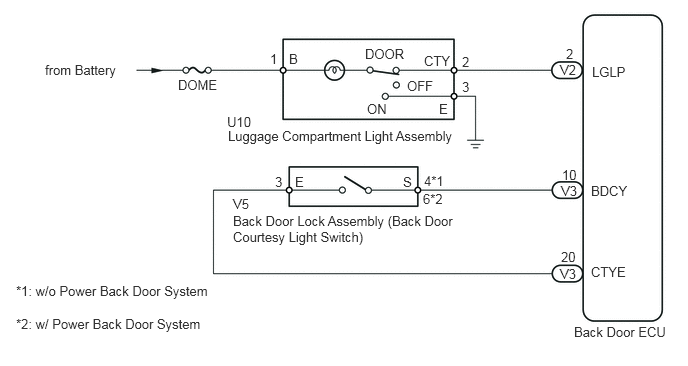
E176429E04
0.469,0.646 1.292,0.823 0.823,0.177 10 false from Battery 1.854,0.802 2.292,0.969 0.438,0.167 10 false DOME 2.813,0.531 2.917,0.719 0.104,0.188 10 false 1 3.01,0.531 3.125,0.708 0.115,0.177 10 false B 3.802,0.479 4.26,0.656 0.458,0.177 10 false DOOR 4.417,0.552 4.76,0.719 0.344,0.167 10 false CTY 4.813,0.563 4.917,0.719 0.104,0.156 10 false 2 5.896,0.479 6.01,0.646 0.115,0.167 10 false 2 4.813,0.823 4.948,1 0.135,0.177 10 false 3 4.24,0.813 4.542,1 0.302,0.188 10 false OFF 3.823,1.052 4.063,1.198 0.24,0.146 10 false ON 2.365,1.188 2.688,1.344 0.323,0.156 10 false U10 2.375,1.333 4.833,1.49 2.458,0.156 10 false Luggage Compartment Light Assembly 2.865,1.813 3,1.969 0.135,0.156 10 false 3 3.073,1.813 3.208,1.958 0.135,0.146 10 false E 4.198,1.813 4.333,1.969 0.135,0.156 10 false S 4.417,1.802 4.667,1.948 0.25,0.146 10 false 4*1 4.406,1.99 4.646,2.167 0.24,0.177 10 false 6*2 2.427,2.042 2.667,2.219 0.24,0.177 10 false V5 2.427,2.219 4.896,2.604 2.469,0.385 10 false Back Door Lock Assembly (Back Door Courtesy Light Switch) 5.833,0.646 6.042,0.823 0.208,0.177 10 false V2 5.854,1.74 6.073,1.896 0.219,0.156 10 false 10 5.844,1.906 6.073,2.094 0.229,0.188 10 false V3 5.844,2.594 6.042,2.781 0.198,0.188 10 false 20 5.833,2.771 6.052,2.927 0.219,0.156 10 false V3 6.167,0.667 6.573,0.906 0.406,0.24 10 false LGLP 6.156,1.906 6.583,2.115 0.427,0.208 10 false BDCY 6.156,2.75 6.563,2.927 0.406,0.177 10 false CTYE 5.979,3.375 7.031,3.688 1.052,0.313 10 false Back Door ECU 0.167,2.948 2.271,3.281 2.104,0.333 10 false *1: w/o Power Back Door System 0.167,3.292 2.167,3.625 2,0.333 10 false *2: w/ Power Back Door System 4.573,1.052 4.719,1.229 0.146,0.177 10 false E

PROCEDURE

1.PERFORM ACTIVE TEST USING TECHSTREAM (LUGGAGE COMPARTMENT LIGHT)
a.

Connect the Techstream to the DLC3.


b.

Turn the ignition switch to ON.


c.

Turn the Techstream on.


d.

Enter the following menus: Body Electrical / Back Door P/W / Active Test / Luggage Compartment Light.


e.

According to the display on the Techstream, check the Active Test.

Back Door P/W
Tester Display Test Part Control Range Diagnostic Note
Luggage Compartment Light Luggage Compartment Light ON or OFF Luggage Compartment Light switch is DOOR

OK:

Luggage Compartment light turns on/off.


OK

2.READ VALUE USING TECHSTREAM (BACK DOOR COURTESY SWITCH)

NG

5.INSPECT FUSE (DOME)
2.READ VALUE USING TECHSTREAM (BACK DOOR COURTESY SWITCH)
a.

Connect the Techstream to the DLC3.


b.

Turn the ignition switch to ON.


c.

Turn the Techstream on.


d.

Enter the following menus: Body Electrical / Back Door P/W / Data List / Back Door Courtesy Switch.


e.

According to the display on the Techstream, read the Data List.

Back Door P/W
Tester Display Measurement Item/Range Normal Condition Diagnostic Note
Back Door Courtesy Switch Back Door Courtesy Switch / ON or OFF ON: Back door opened
OFF: Back door closed
-

OK:

When back door courtesy switch operation is performed, the results are the same as above.


OK

REPLACE BACK DOOR ECU

NG

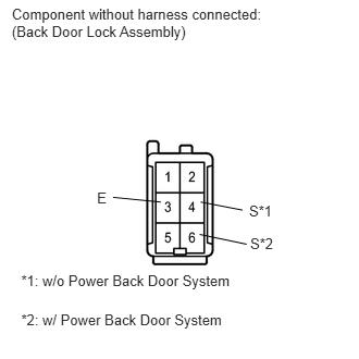
3.INSPECT BACK DOOR LOCK ASSEMBLY (BACK DOOR COURTESY LIGHT SWITCH)
a.
E161579E01
0.113,0.051 2.602,0.407 2.490,0.356 10 Component without harness connected: (Back Door Lock Assembly) 2.385,1.936 2.628,2.083 0.242,0.147 10 S*1 2.396,2.255 2.652,2.440 0.256,0.185 10 S*2 0.929,1.811 1.082,1.984 0.153,0.173 10 E 1.082,1.889 1.539,1.934 false 2.361,2.338 1.912,2.244 false 1.92,1.934 2.321,2.011 false 0.203,2.608 2.286,2.781 2.083,0.174 10 *1: w/o Power Back Door System 0.203,2.98 2.286,3.153 2.083,0.174 10 *2: w/ Power Back Door System

Disconnect the V5 back door lock assembly connector.

b.

Measure the resistance according to the value(s) in the table below.

Standard Resistance:
w/o Power Back Door System
Tester Connection Condition Specified Condition
3 (E) - 4 (S) Back door closed 10 kΩ or higher
Back door opened Below 1 Ω

w/ Power Back Door System
Tester Connection Condition Specified Condition
3 (E) - 6 (S) Back door closed 10 kΩ or higher
Back door opened Below 1 Ω


c.

Reconnect the back door lock assembly connector.


OK

4.CHECK HARNESS AND CONNECTOR (BACK DOOR LOCK ASSEMBLY - BACK DOOR ECU, BODY GROUND)

NG

REPLACE BACK DOOR LOCK ASSEMBLY

4.CHECK HARNESS AND CONNECTOR (BACK DOOR LOCK ASSEMBLY - BACK DOOR ECU, BODY GROUND)
a.

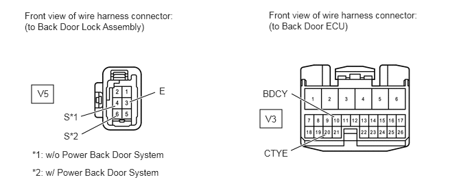
Disconnect the V5 back door lock assembly connector.

E344929E01
0.479,1.292 0.813,1.573 0.333,0.281 3.948,1.667 4.281,1.948 0.333,0.281 1.229,1.771 1.75,1.615 true 1.24,2.042 1.76,1.771 true 1.969,1.552 2.354,1.406 true 4.427,1.427 5.073,1.781 true 4.417,2.292 4.938,2.052 true 0.375,0.156 2.677,0.594 2.302,0.438 10 false Front view of wire harness connector: (to Back Door Lock Assembly) 0.573,1.344 0.906,1.615 0.333,0.271 10 false V5 0.969,1.698 1.24,1.896 0.271,0.198 10 false S*1 0.969,1.99 1.24,2.188 0.271,0.198 10 false S*2 2.417,1.302 2.75,1.573 0.333,0.271 10 false E 0.49,2.271 2.76,2.521 2.271,0.25 10 false *1: w/o Power Back Door System 0.49,2.542 2.74,2.76 2.25,0.219 10 false *2: w/ Power Back Door System 4.083,0.146 6.385,0.583 2.302,0.438 10 false Front view of wire harness connector: (to Back Door ECU) 3.99,1.344 4.531,1.563 0.542,0.219 10 false BDCY 4.01,2.25 4.552,2.469 0.542,0.219 10 false CTYE 4.031,1.729 4.365,2 0.333,0.271 10 false V3


b.

Disconnect the V3 back door ECU connector.


c.

Measure the resistance according to the value(s) in the table below.

Standard Resistance:
w/o Power Back Door System
Tester Connection Condition Specified Condition
V3-10 (BDCY) - V5-4 (S) Always Below 1 Ω
V3-20 (CTYE) - V5-3 (E) Always Below 1 Ω
V5-3 (E) - Body ground Always 10 kΩ or higher
V5-4 (S) - Body ground Always 10 kΩ or higher

w/ Power Back Door System
Tester Connection Condition Specified Condition
V3-10 (BDCY) - V5-6 (S) Always Below 1 Ω
V3-20 (CTYE) - V5-3 (E) Always Below 1 Ω
V5-6 (S) - Body ground Always 10 kΩ or higher
V5-3 (E) - Body ground Always 10 kΩ or higher


d.

Reconnect the back door ECU connector.


e.

Reconnect the back door lock assembly connector.


OK

REPLACE BACK DOOR ECU

NG

REPAIR OR REPLACE HARNESS OR CONNECTOR

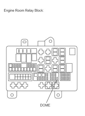
5.INSPECT FUSE (DOME)
a.
E161570E07
2.302,3.219 1.875,4.146 false 0.156,0.333 1.979,0.677 1.823,0.344 10 false Engine Room Relay Block: 1.625,4.156 2.104,4.417 0.479,0.26 10 false DOME

Remove the DOME fuse from the engine room relay block.


b.

Measure the resistance according to the value(s) in the table below.

Standard Resistance:
Tester Connection Condition Specified Condition
DOME fuse Always Below 1 Ω


c.

Reinstall the DOME fuse.


OK

6.INSPECT LUGGAGE COMPARTMENT ROOM LIGHT

NG

REPLACE FUSE

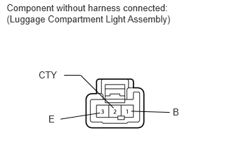
6.INSPECT LUGGAGE COMPARTMENT ROOM LIGHT
a.
E161581E01
0.098,0.031 2.610,0.392 2.512,0.361 10 Component without harness connected: (Luggage Compartment Light Assembly) 2.56,1.588 2.672,1.733 0.112,0.144 10 B 0.572,1.03 0.883,1.174 0.311,0.144 10 CTY 0.718,1.684 0.860,1.833 0.142,0.149 10 E 0.896,1.772 1.483,1.68 false 1.194,1.119 1.682,1.607 false 1.944,1.654 2.514,1.672 false 1.194,1.119 0.95,1.119 false

Remove the luggage compartment room light assembly (See page Vehicle Interior>LIGHTING (INT)>LUGGAGE COMPARTMENT ROOM LIGHT>REMOVAL).


b.

Connect the (+) lead from the battery to terminal 1 and the (-) lead to terminal 2 or 3.


c.

Check that the room light comes on.

Standard Resistance:
Tester Connection Switch Condition Specified Condition
Battery positive (+) →1 (B)
Battery negative (-) → 3 (E)
Luggage compartment light switch ON Room light comes on
Luggage compartment light switch DOOR Room light turns off
Luggage compartment light switch OFF Room light turns off
Battery positive (+) →1 (B)
Battery negative (-) → 2 (CTY)
Luggage room light switch ON Room light turns off
Luggage compartment light switch DOOR Room light comes on
Luggage compartment light switch OFF Room light turns off


d.

Reinstall the luggage compartment room light assembly.


OK

7.CHECK HARNESS AND CONNECTOR (LUGGAGE COMPARTMENT LIGHT - BATTERY, BACK DOOR ECU)

NG

REPLACE LUGGAGE COMPARTMENT ROOM LIGHT

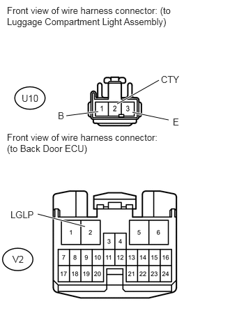
7.CHECK HARNESS AND CONNECTOR (LUGGAGE COMPARTMENT LIGHT - BATTERY, BACK DOOR ECU)
a.
U154064E02
0.99,1.729 1.469,1.667 true 1.75,1.552 2.375,1.198 true 1.979,1.677 2.521,1.792 true 0.563,3.198 1.271,3.385 true 0.104,0.073 2.729,0.813 2.625,0.74 10 false Front view of wire harness connector: (to Luggage Compartment Light Assembly) 0.104,1.969 2.521,2.635 2.417,0.667 10 false Front view of wire harness connector: (to Back Door ECU) 0.865,1.646 0.99,1.802 0.125,0.156 10 false B 2.406,1.104 2.729,1.292 0.323,0.188 10 false CTY 2.583,1.74 2.708,1.885 0.125,0.146 10 false E 0.156,3.125 0.583,3.271 0.427,0.146 10 false LGLP 0.323,1.385 0.604,1.542 0.281,0.156 10 false U10 0.188,3.792 0.469,3.948 0.281,0.156 10 false V2

Disconnect the U10 luggage compartment light assembly connector.


b.

Disconnect the V2 back door ECU connector.


c.

Measure the voltage and resistance according to the value(s) in the table below.

Standard Voltage:
Tester Connection Condition Specified Condition
U10-1 (B) - Body ground Always 11 to 14 V


Standard Resistance:
Tester Connection Switch Condition Specified Condition
U10-2 (CTY) - V2-2 (LGLP) Always Below 1 Ω
U10-3 (E) - Body ground Always 10 kΩ or higher


d.

Reconnect the back door ECU connector.


e.

Reconnect the luggage compartment light assembly connector.


OK

REPLACE BACK DOOR ECU

NG

REPAIR OR REPLACE HARNESS OR CONNECTOR