Home › Vehicle Interior › METER / GAUGE / DISPLAY › METER / GAUGE SYSTEM
RM27L0U _58 Vehicle Interior _049339 METER / GAUGE / DISPLAY _0235844 METER / GAUGE SYSTEM J

METER / GAUGE / DISPLAY  METER / GAUGE SYSTEM  Entire Combination Meter does not Operate  


DESCRIPTION

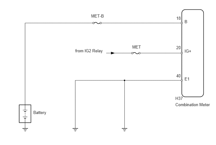
This circuit is the power source circuit for the combination meter. This circuit provides 2 power source types: one is a constant power source mainly used as a backup power source, and other is a power source mainly used for signal transmission. The constant power source is mainly used as a backup power source of the meter CPU. However, it is also used for communication. If a voltage of 12 V is not applied to terminal IG+ when the ignition switch is ON, the indicator will not operate.

WIRING DIAGRAM
E146026E02
5.817,3.188 6.110,3.389 0.293,0.201 10 H37 6.123,0.634 6.619,0.835 0.496,0.201 10 B 5.847,0.523 6.048,0.724 0.201,0.201 10 18 3.023,0.453 3.546,0.654 0.523,0.201 10 MET-B 4.387,1.476 4.754,1.677 0.367,0.201 10 MET 2.497,1.606 3.509,1.807 1.011,0.201 10 from IG2 Relay 1.105,3.653 2.116,3.854 1.011,0.201 10 Battery 6.123,1.611 6.619,1.812 0.496,0.201 10 IG+ 5.847,1.5 6.048,1.701 0.201,0.201 10 20 6.123,2.545 6.619,2.746 0.496,0.201 10 E1 5.847,2.434 6.048,2.635 0.201,0.201 10 40 5.817,3.392 7.049,3.594 1.233,0.201 10 Combination Meter

PROCEDURE

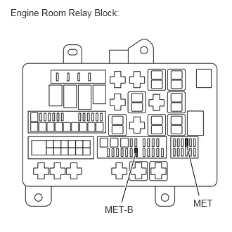
1.INSPECT FUSE (MET, MET-B)
a.
E345045E01
1.802,3 2.01,2.271 true 2.948,2.896 2.771,2.167 true 1.552,3.021 2.031,3.219 0.479,0.198 10 false MET-B 2.865,2.927 3.188,3.125 0.323,0.198 10 false MET 0.156,0.104 1.823,0.302 1.667,0.198 10 false Engine Room Relay Block:

Remove the MET and MET-B fuses from the engine room relay block.


b.

Measure the resistance according to the value(s) in the table below.

Standard Resistance:
Tester Connection Condition Specified Condition
MET fuse Always Below 1 Ω
MET-B fuse Always Below 1 Ω


OK

2.CHECK HARNESS AND CONNECTOR (COMBINATION METER - BATTERY AND BODY GROUND)

NG

CHECK FOR SHORTS IN ALL HARNESSES AND CONNECTORS CONNECTED TO FUSE AND REPLACE FUSE

2.CHECK HARNESS AND CONNECTOR (COMBINATION METER - BATTERY AND BODY GROUND)
a.
U153967E02
1.083,1.448 0.844,1.542 true 0.823,1.229 1.083,1.354 true 0.958,1.031 1.208,1.354 true 0.083,0.021 2.427,0.406 2.344,0.385 10 false Rear view of wire harness connector: (to Combination Meter) 2.656,1.271 2.948,1.438 0.292,0.167 10 false H37 0.792,0.896 0.917,1.063 0.125,0.167 10 false B 0.542,1.135 0.802,1.323 0.26,0.188 10 false IG+ 0.615,1.5 0.813,1.688 0.198,0.188 10 false E1

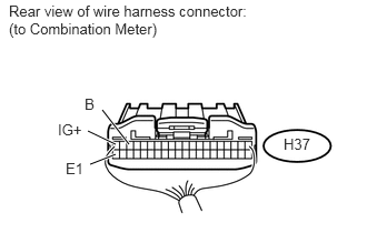
Disconnect the H37 meter connector.


b.

Measure the resistance and voltage according to the value(s) in the table below.

Standard Resistance:
Tester Connection Condition Specified Condition
H37-40 (E1) - Body ground Always Below 1 Ω


Standard Voltage:
Tester Connection Switch Condition Specified Condition
H37-18 (B) - Body ground Always 11 to 14 V
H37-20 (IG+) - Body ground Ignition switch ON 11 to 14 V


OK

REPLACE COMBINATION METER ASSEMBLY

NG

REPAIR OR REPLACE HARNESS OR CONNECTOR