Home › Vehicle Interior › METER / GAUGE / DISPLAY › METER / GAUGE SYSTEM
RM27L0U _58 Vehicle Interior _049339 METER / GAUGE / DISPLAY _0235844 METER / GAUGE SYSTEM J

METER / GAUGE / DISPLAY  METER / GAUGE SYSTEM  Operating Light Control Rheostat does not Change Light Brightness  


DESCRIPTION

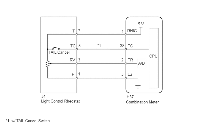
The illumination intensity of the combination meter and accessory meter is increased by turning the knob of the light control rheostat upward, and decreased by turning the knob downward.

WIRING DIAGRAM
E159568E02
4.406,3.479 5.667,3.677 1.26,0.198 10 false Combination Meter 1.438,3.448 2.906,3.646 1.469,0.198 10 false Light Control Rheostat 4.427,3.302 4.74,3.469 0.313,0.167 10 false H37 4.448,0.99 4.802,1.167 0.354,0.177 10 false RHIG 4.25,1.021 4.354,1.177 0.104,0.156 10 false 1 4.469,1.521 4.688,1.677 0.219,0.156 10 false TC 4.198,1.51 4.375,1.677 0.177,0.167 10 false 38 4.469,2.01 4.677,2.167 0.208,0.156 10 false TR 5.219,1.875 5.51,2.063 0.292,0.188 10 false CPU 4.823,0.75 5.063,0.906 0.24,0.156 10 false 5 V 4.24,2.01 4.344,2.188 0.104,0.177 10 false 2 4.458,2.51 4.677,2.708 0.219,0.198 10 false E2 4.24,2.51 4.344,2.688 0.104,0.177 10 false 3 2.531,1 2.646,1.167 0.115,0.167 10 false T 2.729,0.99 2.854,1.146 0.125,0.156 10 false 7 2.458,1.521 2.656,1.677 0.198,0.156 10 false TC 1.698,1.74 2.469,1.917 0.771,0.177 10 false TAIL Cancel 2.74,1.51 2.854,1.677 0.115,0.167 10 false 5 3.406,1.51 3.583,1.688 0.177,0.177 10 false *1 2.438,2.01 2.656,2.177 0.219,0.167 10 false RV 2.729,2.01 2.854,2.198 0.125,0.188 10 false 3 2.51,2.521 2.656,2.698 0.146,0.177 10 false E 2.729,2.5 2.875,2.677 0.146,0.177 10 false 1 1.448,3.281 1.719,3.479 0.271,0.198 10 false J4 0.198,4.135 2.104,4.375 1.906,0.24 10 false *1: w/ TAIL Cancel Switch 4.833,2.125 5.104,2.281 0.271,0.156 10 false A/D

PROCEDURE

1.READ VALUE USING TECHSTREAM (LIGHT CONTROL RHEOSTAT)
a.

Connect the Techstream to the DLC3.


b.

Turn the ignition switch to ON.


c.

Turn the Techstream ON.


d.

Enter the following menus: Body Electrical / Combination Meter / Data List.


e.

According to the display on the Techstream, read the Data List.

Combination Meter
Tester Display Measurement Item/Range Normal Condition Diagnostic Note
TAIL Cancel SW*1 TAIL cancel switch condition/ON or OFF ON: TAIL cancel switch ON
OFF: TAIL cancel switch OFF
-
Rheostat value Light control rheostat switch input/Min.: 0, Max.: 100 Light control rheostat switch is Dark (0) → Bright (100) Unit: %

*1: w/ TAIL Cancel Switch


OK:

Light brightness can be changed within specified range by manual operation.


OK

REPLACE COMBINATION METER ASSEMBLY

NG

2.INSPECT LIGHT CONTROL RHEOSTAT
a.

Remove the light control rheostat (See page Vehicle Interior>METER / GAUGE / DISPLAY>LIGHT CONTROL RHEOSTAT>REMOVAL).


b.

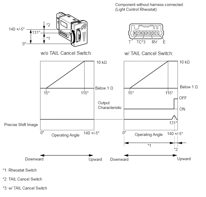
Measure the resistance according to the table below.
U154128E02
1.073,1.083 1.073,1.417 false 1.531,1.198 1.531,1.406 false 1.531,1.167 1.531,0.74 false 4.427,4.969 5.99,4.969 false 6.063,4.969 6.479,4.969 false 4.802,1.177 4.583,1.406 true 5.031,1.177 4.948,1.375 true 5.24,1.167 5.313,1.365 true 5.469,1.156 5.698,1.375 true 0.781,1.438 1.01,1.615 0.229,0.177 10 false 0° 0.302,0.927 1.01,1.104 0.708,0.177 10 false 140 +/-5° 1.115,1.042 1.49,1.219 0.375,0.177 10 false 131° 1.615,1.25 1.771,1.406 0.156,0.156 10 false *1 1.615,0.781 1.771,0.938 0.156,0.156 10 false *2 4.688,4.594 5.74,4.771 1.052,0.177 10 false Operating Angle 4.448,3.146 4.813,3.313 0.365,0.167 10 false 15° 5.75,3.146 6.167,3.313 0.417,0.167 10 false 115° 1.521,3.146 1.885,3.313 0.365,0.167 10 false 15° 2.813,3.146 3.229,3.313 0.417,0.167 10 false 115° 4.26,4.531 4.448,4.698 0.188,0.167 10 true 0° 6.26,2.938 6.958,3.083 0.698,0.146 10 false Below 1 Ω 3.313,2.979 4.01,3.125 0.698,0.146 10 false Below 1 Ω 6.24,2.073 6.656,2.219 0.417,0.146 10 false 10 kΩ 3.354,2.083 3.771,2.229 0.417,0.146 10 false 10 kΩ 3.833,5.458 4.552,5.625 0.719,0.167 10 false Downward 0.875,5.448 1.552,5.615 0.677,0.167 10 false Downward 6.167,5.438 6.75,5.615 0.583,0.177 10 false Upward 3.083,5.458 3.573,5.635 0.49,0.177 10 false Upward 5.885,4.188 6.167,4.354 0.281,0.167 10 true 131° 6.229,3.323 7.042,3.625 0.813,0.302 10 false OFF 6.24,3.708 7.01,3.896 0.771,0.188 10 false ON 0.146,4.25 1.396,4.438 1.25,0.188 10 false Precise Shift Image 3.406,3.49 4.323,3.99 0.917,0.5 10 false Output Characteristic 5.135,4.979 5.292,5.135 0.156,0.156 10 false *1 6.052,5.115 6.208,5.271 0.156,0.156 10 false *2 5.813,4.563 6.396,4.74 0.583,0.177 10 true 140 +/-5° 1.792,4.615 2.844,4.792 1.052,0.177 10 false Operating Angle 1.406,4.531 1.635,4.708 0.229,0.177 10 false 0° 2.906,4.542 3.615,4.719 0.708,0.177 10 false 140 +/-5° 0.094,6.146 1.573,6.302 1.479,0.156 10 false *2: TAIL Cancel Switch 0.094,5.833 1.365,5.99 1.271,0.156 10 false *1: Rheostat Switch 4.01,0.073 6.531,0.5 2.521,0.427 10 false Component without harness connected: (Light Control Rheostat) 4.469,1.375 4.698,1.552 0.229,0.177 10 false T 4.75,1.375 5.167,1.552 0.417,0.177 10 false TC*3 0.094,6.458 1.771,6.635 1.677,0.177 10 false *3: w/ TAIL Cancel Switch 4.333,1.75 6.281,1.927 1.948,0.177 12 false w/ TAIL Cancel Switch: 5.281,1.375 5.51,1.552 0.229,0.177 10 false RV 5.667,1.375 5.896,1.552 0.229,0.177 10 false E 1.417,1.74 3.302,1.917 1.885,0.177 12 false w/o TAIL Cancel Switch:

Standard Resistance:
w/o TAIL Cancel Switch
Tester Connection Condition Specified Condition
3 (RV) - 1 (E) Downward → Upward See illustration
7 (T) - 1 (E) Always 8 to 12 kΩ

w/ TAIL Cancel Switch
Tester Connection Condition Specified Condition
3 (RV) - 1 (E) Downward → Upward See illustration
5 (TC) - 7 (T) Downward → Upward 10 kΩ or higher → Below 1 Ω
7 (T) - 1 (E) Always 8 to 12 kΩ


OK

3.CHECK HARNESS AND CONNECTOR (COMBINATION METER - LIGHT CONTROL RHEOSTAT)

NG

3.CHECK HARNESS AND CONNECTOR (COMBINATION METER - LIGHT CONTROL RHEOSTAT)
a.

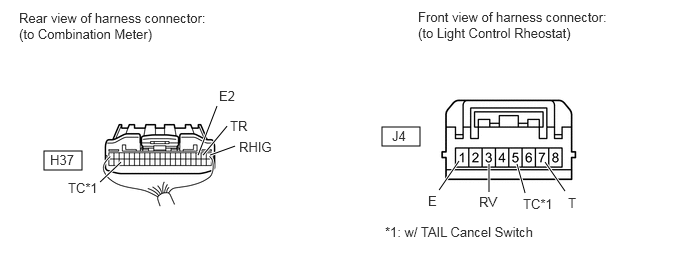
Disconnect the H37 meter connector.

E345046E01
0.458,1.573 0.854,1.771 0.396,0.198 3.979,1.323 4.375,1.521 0.396,0.198 4.573,1.979 4.781,1.677 true 2.063,1.615 2.26,1.104 true 2.115,1.615 2.365,1.313 true 2.188,1.615 2.448,1.521 true 5.094,2 5.094,1.708 true 5.469,2.01 5.385,1.708 true 5.885,1.99 5.677,1.688 true 1.042,1.896 1.26,1.688 true 0.198,0.104 2.177,0.458 1.979,0.354 10 false Rear view of harness connector: (to Combination Meter) 0.521,1.583 0.813,1.781 0.292,0.198 10 false H37 0.708,1.875 1,2.073 0.292,0.198 10 false TC*1 2.281,0.917 2.573,1.115 0.292,0.198 10 false E2 2.396,1.229 2.625,1.406 0.229,0.177 10 false TR 2.49,1.448 2.854,1.615 0.365,0.167 10 false RHIG 4.354,0.094 6.333,0.448 1.979,0.354 10 false Front view of harness connector: (to Light Control Rheostat) 4.083,1.333 4.281,1.521 0.198,0.188 10 false J4 4.458,2.01 4.594,2.198 0.135,0.188 10 false E 4.99,2.021 5.198,2.208 0.208,0.188 10 false RV 5.448,2.042 5.781,2.229 0.333,0.188 10 false TC*1 5.917,2.031 6.052,2.219 0.135,0.188 10 false T 4.01,2.333 5.594,2.531 1.583,0.198 10 false *1: w/ TAIL Cancel Switch


b.

Disconnect the J4 rheostat connector.


c.

Measure the resistance according to the value(s) in the table below.

Standard Resistance:
w/o TAIL Cancel Switch
Tester Connection Condition Specified Condition
H37-1 (RHIG) - J4-7 (T) Always Below 1 Ω
H37-2 (TR) - J4-3 (RV) Always Below 1 Ω
H37-3 (E2) - J4-1 (E) Always Below 1 Ω

w/ TAIL Cancel Switch
Tester Connection Condition Specified Condition
H37-1 (RHIG) - J4-7 (T) Always Below 1 Ω
H37-2 (TR) - J4-3 (RV) Always Below 1 Ω
H37-3 (E2) - J4-1 (E) Always Below 1 Ω
H37-38 (TC) - J4-5 (TC) Always Below 1 Ω


OK

REPLACE COMBINATION METER ASSEMBLY

NG

REPAIR OR REPLACE HARNESS OR CONNECTOR