Home › Vehicle Interior › METER / GAUGE / DISPLAY › METER / GAUGE SYSTEM
RM27L0U _58 Vehicle Interior _049339 METER / GAUGE / DISPLAY _0235844 METER / GAUGE SYSTEM J

METER / GAUGE / DISPLAY  METER / GAUGE SYSTEM  Meter Illumination is Always Dark  


DESCRIPTION

When the ignition switch is turned to ACC or ON, the accessory meter operates as follows.

The accessory meter receives light control switch signals and combination meter signals, and performs illumination dim operations.

WIRING DIAGRAM
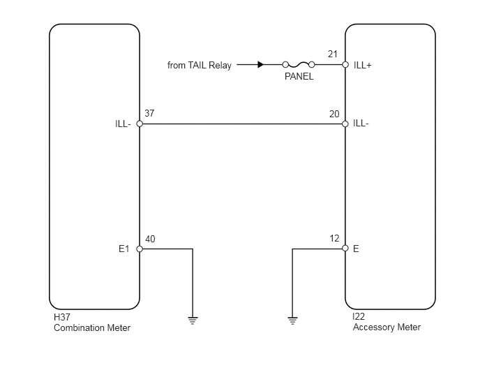
E345047E01
1.719,1.76 1.99,1.938 0.271,0.177 10 false ILL- 1.771,3.625 2.01,3.802 0.24,0.177 10 false E1 2.156,1.604 2.354,1.781 0.198,0.177 10 false 37 2.167,3.479 2.365,3.656 0.198,0.177 10 false 40 2.5,0.885 3.51,1.094 1.01,0.208 10 false from TAIL Relay 4.25,1.052 4.771,1.229 0.521,0.177 10 false PANEL 4.896,0.719 5.094,0.896 0.198,0.177 10 false 21 5.281,0.885 5.552,1.063 0.271,0.177 10 false ILL+ 4.917,3.469 5.115,3.646 0.198,0.177 10 false 12 5.271,1.75 5.542,1.927 0.271,0.177 10 false ILL- 4.917,1.615 5.115,1.792 0.198,0.177 10 false 20 5.271,3.625 5.51,3.802 0.24,0.177 10 false E 0.802,4.646 1.083,4.833 0.281,0.188 10 false H37 0.802,4.802 2.021,5 1.219,0.198 10 false Combination Meter 5.26,4.635 5.5,4.813 0.24,0.177 10 false I22 5.271,4.792 6.365,4.979 1.094,0.188 10 false Accessory Meter

PROCEDURE

1.CHECK ILLUMINATION FUNCTION
a.

Check the illumination function.

Result
Result Proceed to
Accessory meter illumination is always dark A
Combination meter illumination is always dark B


A

2.INSPECT FUSE (PANEL)

B

2.INSPECT FUSE (PANEL)
a.
E345048E01
1.24,1.042 1.573,0.479 false 0.198,0.115 1.26,0.313 1.063,0.198 10 false Main Body ECU: 1.646,0.354 2.125,0.552 0.479,0.198 10 false PANEL

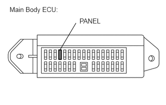
Remove the PANEL fuse from the main body ECU.


b.

Measure the resistance according to the value(s) in the table below.

Standard Resistance:
Tester Connection Condition Specified Condition
PANEL fuse Always Below 1 Ω


OK

3.CHECK HARNESS AND CONNECTOR (ACCESSORY METER - BATTERY)

NG

CHECK FOR SHORTS IN ALL HARNESSES AND CONNECTORS CONNECTED TO FUSE AND REPLACE FUSE

3.CHECK HARNESS AND CONNECTOR (ACCESSORY METER - BATTERY)
a.
U153996E01
0.068,0.049 2.411,0.393 2.342,0.344 10 Front view of wire harness connector: (to Accessory Meter) 1.871,1.753 2.163,1.909 0.292,0.156 10 ILL+ 2.042,1.472 2.042,1.741 false 0.355,1.209 0.575,1.361 0.219,0.152 10 I22

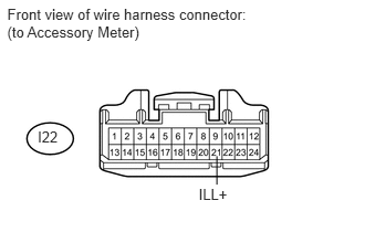
Disconnect the I22 accessory meter connector.


b.

Measure the voltage according to the value(s) in the table below.

Standard Voltage:
Tester Connection Switch Condition Specified Condition
I22-21 (ILL+) - Body ground Light control switch ON 11 to 14 V


OK

4.CHECK HARNESS AND CONNECTOR (COMBINATION METER - ACCESSORY METER AND BODY GROUND)

NG

REPAIR OR REPLACE HARNESS OR CONNECTOR

4.CHECK HARNESS AND CONNECTOR (COMBINATION METER - ACCESSORY METER AND BODY GROUND)
a.
U153999E02
2.438,1.49 2.438,1.844 true 1.885,3.844 1.885,4.177 true 2.813,1.458 3.063,1.458 true 0.177,0.104 2.51,0.458 2.333,0.354 10 false Front view of wire harness connector: (to Combination Meter) 2.365,1.865 2.635,2.01 0.271,0.146 10 false ILL- 0.177,2.323 2.51,2.677 2.333,0.354 10 false Front view of wire harness connector: (to Accessory Meter) 1.823,4.198 2.083,4.344 0.26,0.146 10 false ILL- 3.146,1.375 3.344,1.521 0.198,0.146 10 false E1 0.146,1.313 0.417,1.49 0.271,0.177 10 false H37 0.354,3.594 0.563,3.771 0.208,0.177 10 false I22

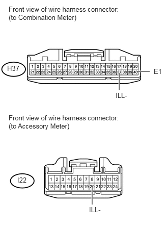
Disconnect the H37 combination meter connector.


b.

Disconnect the I22 accessory meter connector.


c.

Measure the resistance according to the value(s) in the table below.

Standard Resistance:
Tester Connection Condition Specified Condition
H37-37 (ILL-) - I22-20 (ILL-) Always Below 1 Ω
H37-37 (ILL-) - Body ground Always 10 kΩ or higher
H37-40 (E1) - Body ground Always Below 1 Ω


OK

5.REPLACE ACCESSORY METER ASSEMBLY

NG

REPAIR OR REPLACE HARNESS OR CONNECTOR

5.REPLACE ACCESSORY METER ASSEMBLY
a.

Temporarily replace the accessory meter with a new or normally functioning one (See page Vehicle Interior>METER / GAUGE / DISPLAY>ACCESSORY METER>REMOVAL).


NEXT

6.CHECK ACCESSORY METER ASSEMBLY (OPERATION)
a.

Check the accessory meter operation.

OK:

Operation of the accessory meter returns to normal.


OK

END (ACCESSORY METER IS DEFECTIVE)

NG

REPLACE COMBINATION METER ASSEMBLY